Prefabricated Vertical Drains: Optimizing Soil Stabilization with PGATECH Group

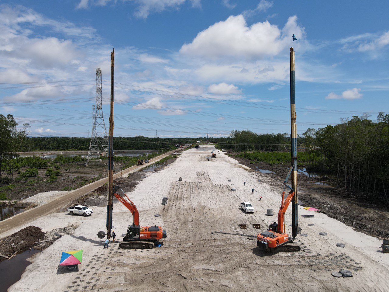
Prefabricated Vertical Drains (PVDs) are a cornerstone of modern soil stabilization techniques. At the PGATECH Group, we offer advanced PVD solutions designed to accelerate soil consolidation, improve ground stability, and enhance the performance of your construction projects. In this detailed article, we will cover what PVDs are, their history, function, advantages, applications, desirability, and the problems they address.

What are Prefabricated Vertical Drains?

Prefabricated Vertical Drains, commonly known as PVDs, are synthetic drainage paths installed vertically into soft, compressible soil to facilitate the expulsion of excess pore water. PVDs consist of a plastic core wrapped in a geotextile filter, which allows water to flow through while preventing soil particles from clogging the drain. This technology is used to accelerate the consolidation process of soft soils, making them more stable for construction.

History of Prefabricated Vertical Drains

The concept of vertical drainage dates back to the early 20th century, but the use of prefabricated synthetic drains began in the 1970s. Initially developed in Europe, PVDs quickly gained popularity due to their effectiveness and ease of installation compared to traditional sand drains. Over the decades, advancements in materials and installation techniques have further improved the efficiency and reliability of PVDs.

What is the Function/Purpose of Prefabricated Vertical Drains?

The primary function of PVDs is to expedite the consolidation of soft, water-saturated soils. Key purposes include:


  • Accelerating Soil Consolidation: By providing a pathway for excess pore water to escape, PVDs speed up the consolidation process, reducing the time required for soil to achieve desired strength and stability.
  • Reducing Settlement Time: PVDs significantly shorten the settlement period of soft soils, enabling faster construction progress.
  • Enhancing Soil Stability: Improved drainage and consolidation result in stronger and more stable ground, capable of supporting structures.

What Do Prefabricated Vertical Drains Replace?

PVDs serve as an effective alternative to traditional soil improvement methods, such as:


  • Sand Drains: While effective, sand drains are labor-intensive and require extensive material handling.
  • Preloading Alone: Preloading without PVDs can be slow, as the natural consolidation process is lengthy.
  • Deep Foundations: In some cases, PVDs can reduce the need for deep foundations by improving the ground’s load-bearing capacity.

These traditional methods can be costly, time-consuming, and less efficient compared to using PVDs.

    Advantages of Prefabricated Vertical Drains

    PVDs offer numerous advantages, including:


    • Cost-Effectiveness: Lower installation costs compared to other soil improvement techniques.
    • Time Efficiency: Accelerates the consolidation process, reducing project timelines.
    • Ease of Installation: Quick and straightforward installation using specialized equipment.
    • Flexibility: Suitable for a variety of soil types and project conditions.
    • Environmental Benefits: Minimizes the need for extensive excavation and material transport.

    Where are Prefabricated Vertical Drains Applicable?

    PVDs are applicable in a wide range of scenarios, such as:


    • Infrastructure Projects: Roads, highways, railways, and airports where soft soils are prevalent.
    • Land Reclamation: Coastal areas and reclaimed land requiring rapid stabilization.
    • Construction Sites: Building foundations on soft or waterlogged soils.
    • Embankments: Stabilizing embankments for transportation and flood control structures.
    • Industrial Sites: Preparing sites for heavy industrial structures.

    What Makes Prefabricated Vertical Drains Desirable?

    The desirability of PVDs stems from their efficiency, effectiveness, and versatility. Key factors include:


    • Speed: Rapid consolidation allows for quicker project completion.
    • Economic Savings: Reduces the overall cost of soil improvement and construction.
    • Minimal Disruption: Installation is less intrusive compared to traditional methods.
    • Reliability: Proven performance in a variety of soil conditions and project types.
    • Sustainability: Environmentally friendly solution that reduces waste and resource consumption.

    Problems Addressed by Prefabricated Vertical Drains

    PVDs effectively address several soil-related challenges, including:


    • Excessive Settlement: Accelerates soil consolidation, reducing the risk of uneven settlement.
    • Poor Drainage: Improves water drainage in waterlogged soils, enhancing stability.
    • Long Construction Delays: Speeds up the consolidation process, allowing for faster construction.
    • Soil Instability: Increases soil strength and stability, preventing potential ground failure.
    • High Construction Costs: Offers a cost-effective alternative to traditional soil stabilization methods.

    Conclusion

    At PGATECH Group, we are dedicated to providing innovative Prefabricated Vertical Drain solutions that enhance the stability and safety of your construction projects. Our expertise and advanced techniques ensure that even the most challenging soil conditions are effectively managed. For more information about our PVD services, please contact us today.
    Sieve Analysis

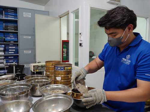
    Sieve analysis is a mechanical method in soil testing that determines the particle size distribution of a soil sample. This process involves passing the samples through sieves of standard sizes. The sieve sizes progressively become smaller from 125 mm all the way to 75 microns. Specific sizes and numbering of these sieves are:

    Designation / Sieve No.

    Opening Size (mm)

    5 in

    125

    3.5 in

    90

    2.5 in

    63

    2 in

    50

    1.5 in

    37.5

    1 in

    25

    ¾ in

    19

    ⅜ in

    9.5

    ¼ in

    6.3

    No. 4

    4.75

    No. 8

    2.36

    No. 16

    1.18

    No. 30

    600 microns

    No. 50

    300 microns

    No. 100

    150 microns

    No. 200

    75 microns

    To ensure quality and accuracy, a standard procedure is followed.

    1. Sample Collection

    The sample should be representative of site conditions and must be sufficient to ensure accuracy in the analysis.

    2. Sieves

    Standard sieves that meet specifications are stacked in ascending order of mesh size.

    3. Sieving Process

    The sample is placed on top of the sieve stack and is then shaken for a fixed duration. Shaking must have a pattern and should be uniform all throughout the process.

    4. Weighing

    After the sieving process, the sample retained on each sieve is measured by the difference between the final weight and the empty sieve weight. The weight of material in each sieve is recorded.

    5. Particle Size Distribution

    Using the recorded weight, the percentage of each size can be calculated. These percentages are then plotted with the sieve opening sizes on a particle size distribution curve.

    This method is crucial in evaluating soil properties and its suitability for various engineering applications.

    Rebar Testing

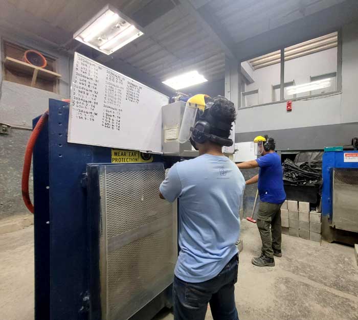
    Rebar testing involves the examination and evaluation of reinforcing bars, commonly referred to as rebars, utilized in construction to provide tensile strength as reinforcement to reinforced concrete components like foundations, columns, beams, and walls. These rebars play a critical role in reinforcing the concrete and enhancing its overall structural integrity.

    The primary objective of rebar testing is to ensure that the rebars utilized in construction projects meet the required quality and performance standards. To achieve this, a variety of non-destructive and destructive testing methods are applied to assess the rebars’ characteristics, including their dimensions, chemical composition, tensile strength, and adherence to pertinent standards and specifications.

    The Rebar undergoes a series of tests for evaluation:

     1. Visual Inspection: Visual inspection is a critical step in rebar testing that involves carefully examining the surface of the rebars to identify any visible defects or irregularities. This includes checking for signs of excessive rust, corrosion, improper bending, or any other surface anomalies that may compromise the integrity of the rebars and the concrete structure they reinforce.

    2. Chemical Analysis: Rebar samples undergo chemical analysis to determine their composition and verify the levels of essential elements, such as carbon and manganese. This test ensures that the rebars comply with material standards and specifications, as the correct chemical composition is crucial for their strength and durability.

    3. Tensile Testing: Tensile strength tests are carried out on rebar samples to assess their ability to withstand tension without breaking. This test is of paramount importance as it evaluates the rebars’ capacity to resist forces and stresses within the reinforced concrete member, ensuring its load-carrying capability.

    4. Bend Test: The bend test evaluates the rebar’s ductility by subjecting it to controlled bending. This helps assess the rebar’s ability to endure deformation without fracturing, which is essential for its flexural performance in the reinforced concrete structural members under various loading conditions.

    Concrete Compression Test

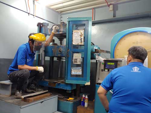
    Concrete compression testing is a fundamental test procedure for civil engineering and construction quality control and assurance used to evaluate the strength and quality of concrete. This procedure involves applying a compressive load to a cylindrical specimen until failure occurs. It is conducted in a controlled laboratory setting adhering to specific standards and protocols.

    The results of concrete compression testing is focal in assessing the load-carrying capacity and structural performance of concrete in various construction applications, including buildings, bridges, pavements, and infrastructure projects. Structural and field engineers rely on these test outcomes to verify that the concrete meets the necessary strength and safety requirements.

    Concrete testing generally follows a procedure that involves the following:


    Sample Preparation:

    Concrete specimens are cast in standardized molds, typically cylinders with a diameter of 150 mm (6 inches) and a height of 300 mm (12 inches). The specimens undergo careful compaction and curing under controlled conditions to achieve the desired strength.


    Testing Apparatus:

    The prepared concrete specimens are placed in a compression testing machine, which applies a progressively increasing load to the specimen. Equipped with load cells and a digital display, the machine accurately measures the applied force.


    Loading Procedure:

    The test commences with a pre-loading phase, during which a small load is applied to eliminate any irregularities or gaps between the specimen and the testing machine. Subsequently, the main loading phase ensues, gradually increasing the load at a specified rate until the concrete sample reaches failure.


    Failure Criteria:
    Failure of the concrete specimen is determined when it can no longer withstand the increasing load, causing the measured resistance to decrease. The maximum load the sample sustained before failure occurs is recorded as the compressive strength of the concrete.

    ISO Accredited Materials Testing Laboratory

    An ISO-accredited materials testing laboratory is a lab that has received official certification for meeting the standards and requirements established by the International Organization for Standardization (ISO). ISO is an independent global organization that develops and publishes standards to ensure consistency, quality, and safety across various industries and sectors.

    To obtain ISO accreditation, a materials testing laboratory undergoes a rigorous evaluation conducted by an independent accreditation body. The lab must demonstrate its competence, technical proficiency, and adherence to specific ISO standards relevant to its field of testing. The accreditation process involves a thorough assessment of the lab’s management system, equipment, staff qualifications, testing procedures, quality control measures, and data reporting practices.

    Earning ISO accreditation is a significant accomplishment that validates the laboratory’s ability to produce precise and reliable test results. It provides assurance to clients, regulators, and other stakeholders that the lab operates with a high level of proficiency and complies with globally recognized standards. The ISO accreditation typically includes a defined scope, specifying the types of materials testing the lab is accredited to perform.

    For materials testing laboratories, ISO/IEC 17025 is the standard commonly used for accreditation. This standard outlines the general requirements for the competence of testing and calibration laboratories and covers aspects such as staff qualifications, equipment calibration, testing methods, quality assurance, and results reporting. By obtaining ISO/IEC 17025 accreditation, materials testing laboratories demonstrate their dedication to providing accurate and dependable test data to support industries, engineering projects, construction, and research endeavors.

    Philippine GeoAnalytics Inc is the first ISO-accredited testing laboratory in the Philippines and continues to provide testing services that are compliant with international standards. We strive and remain to be the trusted testing laboratory of choice.