Geosynthetic Reinforced Soils (GRS): Revolutionizing Earth Structures and Infrastructure

What are Geosynthetic Reinforced Soils (GRS)

Geosynthetic Reinforced Soils (GRS) are composite materials used in civil engineering projects where geosynthetics enhance soil stability and strength. GRS typically involves layering geosynthetic materials, specifically geogrids, within the soil mass to reinforce the compacted soil layers. The goal is to provide added strength and control over soil movement, particularly in structures like retaining walls, embankments, and roadways. By using these materials, engineers can improve load-bearing capacity, increase the durability of structures, and reduce the overall construction cost.

History of Geosynthetic Reinforced Soils (GRS)

Concrete Canvas was developed in 2004 by engineering graduates from the University of Cambridge, UK. Initially conceived as a rapid-deployable shelter for military applications, it quickly gained recognition for its broader potential in civil engineering and construction. Since its commercialization, Concrete Canvas has been used worldwide in diverse projects, proving its versatility and effectiveness. As the official distributors in the Philippines, PGATECH Group has been at the forefront of introducing and implementing this innovative product in the local market.

In the 1980s and 1990s, the use of geosynthetics became more widespread, with a focus on improving the efficiency and stability of soil-based structures. Over the years, testing and trials across different regions demonstrated the ability of GRS to provide better control over soil behavior, ultimately positioning it as a more reliable and affordable alternative to traditional soil stabilization methods.

What is the Mechanism of Geosynthetic Reinforced Soils (GRS)

The mechanism behind GRS lies in the interaction between the geosynthetic material and the surrounding soil. The geogrids act as a reinforcing agent, resisting tensile forces within the soil, which helps to prevent excessive deformations and ultimate shear failure from sustained or seismic loads. This reinforcement effectively reduces the chances of soil shifting, slumping, or other settlement forms, making the overall structure more stable.


The primary mechanisms at play include:


  • Load Distribution: The geosynthetic material helps distribute the tensile forces over a larger area, reducing stress concentration and preventing soil failure.
  • Tensile Reinforcement: The geosynthetic material provides additional tensile strength, improving the soil’s overall ability to resist forces like shear and compression.
  • Soil Encapsulation: The geogrid layers tend to hold the soil together, preventing internal erosion, separation, and degradation over time.
  • Frictional Interaction: The friction between the geosynthetic material and the soil enhances stability and prevents movement under external loads.

Advantages of Geosynthetic Reinforced Soils (GRS)

GRS offers several significant advantages that make it a preferred choice in construction and civil engineering applications:


  • Cost-Effectiveness: GRS can reduce overall construction costs by minimizing the need for traditional, more expensive soil reinforcement such as steel strips.
  • Increased Stability: By reinforcing soil with geogrids, structures such as retaining walls and embankments achieve more excellent stability and longevity, especially with the more distributed loads carried by uniaxial geogrids.
  • Durability and Longevity: Geosynthetic materials are designed to withstand harsh environmental conditions, ensuring that GRS systems last longer with minimal maintenance. The material does not undergo corrosion and is UV-stabilized.
  • Speed of Construction: Using geosynthetics allows for faster installation than traditional methods, speeding up the overall construction timeline.
  • Environmental Benefits: Geosynthetics help reduce the environmental impact by using locally available soil and reducing the need for importing large amounts of granular materials, such as gravel and stone.
  • Adaptability to Various Soil Conditions: GRS is versatile and can be used in varying soil types, including weak, soft, and compressible soils, as determined from laboratory tests.

Where are Geosynthetic Reinforced Soils Most Applicable

GRS is most commonly applied in a wide range of construction and civil engineering projects where soil stabilization is essential. Some of the key applications include:


  • Retaining Walls: GRS is commonly used to construct cost-effective and durable retaining walls that prevent soil erosion and ensure the stability of sloped terrains.
  • Embankments: In roadways, railways, and highways, GRS is utilized to reinforce embankments and reduce total settlement over time.
  • Bridge Abutments: GRS helps stabilize bridge abutments, providing a solid, and ductile foundation for the bridge structure.
  • Landslide Stabilization: GRS can be used to stabilize hillsides prone to landslides, providing long-term solutions for slope stabilization.
  • Road Construction: GRS applications can improve the bearing capacity of roads, reducing the need for expensive subgrade material replacement and improving the longevity of the infrastructure.
  • Landfills and Waste Containment: Geosynthetics help prevent soil erosion and ensure the stability of landfills and waste containment areas.

Geosynthetic Reinforced Soils (GRS) in the Philippines

In the Philippines, where a significant portion of the infrastructure is located in areas prone to natural disasters such as typhoons, flooding, and earthquakes, GRS technology, along with its ductility, presents a viable and sustainable solution for improving ground stability. Its ability to enhance soil stability while remaining cost-effective and environmentally friendly makes it an attractive option for large-scale infrastructure projects, particularly in regions where soil conditions can be challenging.

GRS is also a powerful tool in addressing the country’s infrastructure development needs, especially in areas with limited resources. By incorporating GRS systems in the design and construction of retaining walls, embankments, and roadways, the Philippines can improve the safety and durability of its infrastructure while reducing overall construction costs. As the technology continues to evolve, GRS is poised to become an essential part of modern civil engineering solutions, helping to build more substantial, more resilient structures for the future. And PGATech is at the forefront of implementing GRS technology with its decades of experience in using this technique locally, across the archipelago.

Soil Nailing and Shotcreting

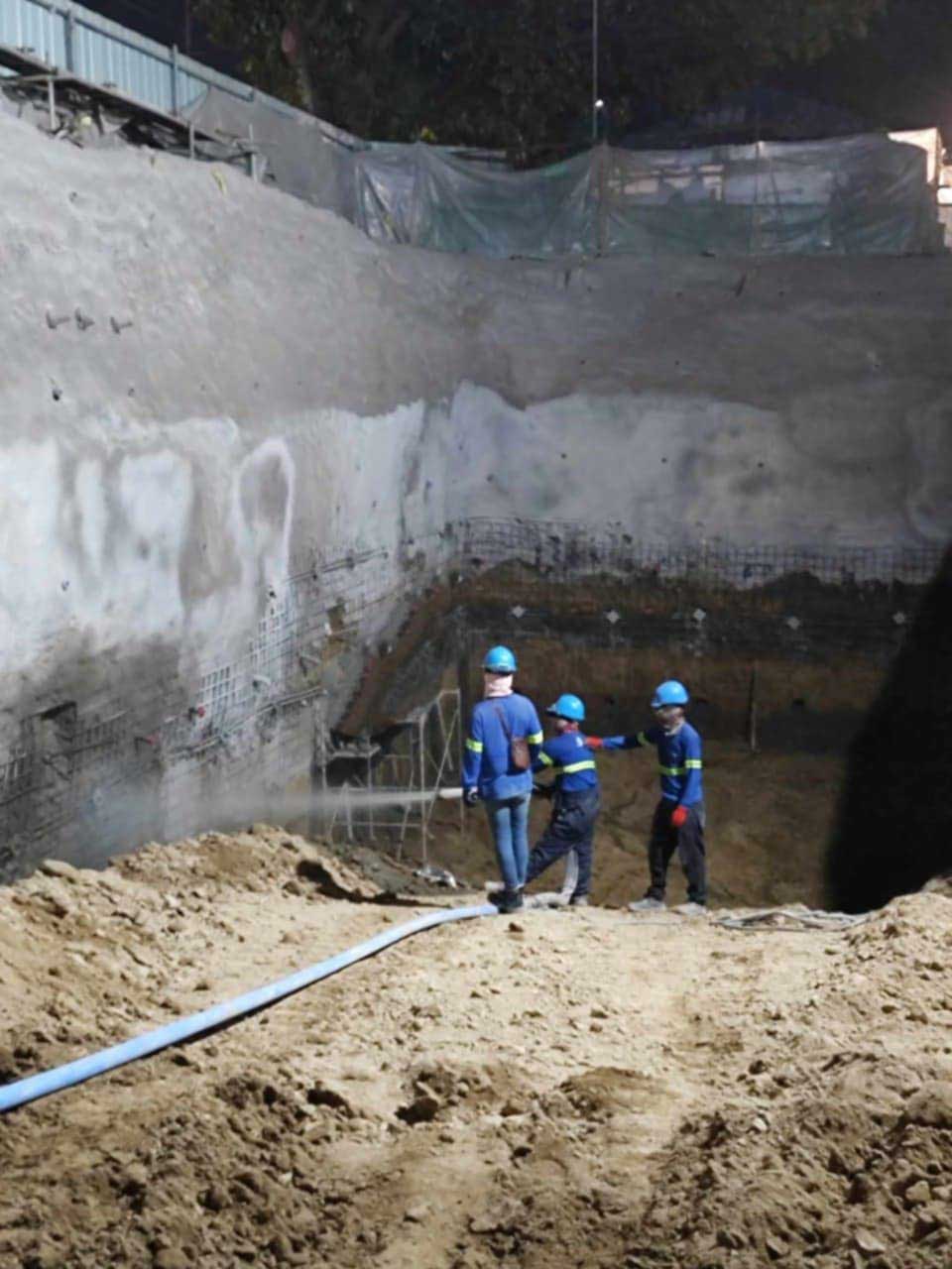
PETER GROUND IMPROVEMENT INC. (PGII) is one of the pioneers of soil nailing and shotcreting in the
Philippines.

Soil nailing is a procedure by which steel reinforcement is installed on a soil mass to mobilize frictional
resistance along the soil nail interface. The shear and pullout resistance of the nail is mobilized to prevent slides or shear failures in the soil. The resistance strengthens and reinforces the soil mass.

The soil nails are “passive” reinforcements or inclusions. The term “passive” means that the soil nails are not pretensioned (as tiebacks or anchors) when they are installed. The nail rebars are forced into
tension as the ground deforms laterally in response to the loss of support caused by continued excavation or by insufficient shear strength in the supporting soil mass. The grouting of the nail increases the overall shear strength, limits the displacement during and after excavation by providing a bigger area for friction to build up. A structural facing (commonly shotcrete) connected to the nails is used when the slope angle exceeds a predetermined critical value or when environmental conditions would cause deterioration of the reinforced soil over its design life.

Concrete Canvas and Hydro GCCM installed for Ditch Lining Project

Concrete Canvas® (CC), is a flexible, concrete impregnated fabric that hardens when hydrated to form a thin, durable, waterproof and fire-resistant concrete layer. Concrete Canvas® allows concrete lining
construction without the need for plant or mixing equipment.

Recently, CC Hydro™ was introduced to the market to address the need for a geomembrane-lined GCCM to create flexible yet hard and impermeable lining materials for projects wherein the need to contain hydrocarbons and other toxic substances is of paramount importance.

Concrete Canvas Applications:

Ditch Lining can be rapidly unrolled to form a ditch or channel lining. It is significantly quicker, easier, and less expensive to install than conventional concrete ditch lining and requires no specialist plant
equipment. CC can be installed at a rate of 200 sqm/hr. by a 3-man team.

Slope Protection can be used to rapidly stabilize and protect slopes against surface erosion as a replacement for shotcrete and steel mesh systems. It is faster to install, lower in cost and requires less specialist plant equipment. CC also helps eliminate the risks associated with shotcrete rebound and debris.

Bund Lining provides a cost-effective alternative to poured or sprayed concrete for lining secondary containment bunds. It also acts as an effective weed barrier, reducing maintenance costs as well as providing additional levels of impermeability and fire protection. Its ability to be installed quickly reduces time on site, while the availability of man-portable rolls allows for installation in areas with reduced access and logistic constraints.

Concrete Remediation can be used to rapidly reline and refurbish existing concrete structures suffering from environmental degradation, abrasion damage and cracking.

Culvert Lining can be used as a cost-effective alternative to bitumen spraying or rebuilding damaged or worn-out culverts, while offering a durable means of providing erosion protection.

Sieve Analysis

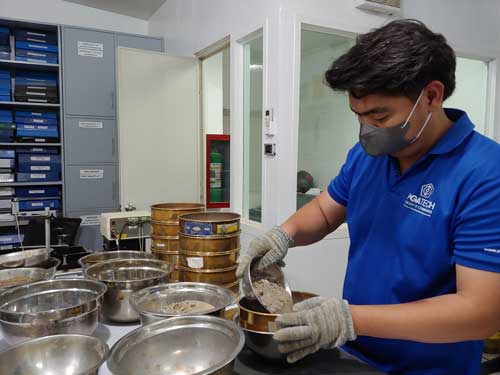
Sieve analysis is a mechanical method in soil testing that determines the particle size distribution of a soil sample. This process involves passing the samples through sieves of standard sizes. The sieve sizes progressively become smaller from 125 mm all the way to 75 microns. Specific sizes and numbering of these sieves are:

Designation / Sieve No.

Opening Size (mm)

5 in

125

3.5 in

90

2.5 in

63

2 in

50

1.5 in

37.5

1 in

25

¾ in

19

⅜ in

9.5

¼ in

6.3

No. 4

4.75

No. 8

2.36

No. 16

1.18

No. 30

600 microns

No. 50

300 microns

No. 100

150 microns

No. 200

75 microns

To ensure quality and accuracy, a standard procedure is followed.

1. Sample Collection

The sample should be representative of site conditions and must be sufficient to ensure accuracy in the analysis.

2. Sieves

Standard sieves that meet specifications are stacked in ascending order of mesh size.

3. Sieving Process

The sample is placed on top of the sieve stack and is then shaken for a fixed duration. Shaking must have a pattern and should be uniform all throughout the process.

4. Weighing

After the sieving process, the sample retained on each sieve is measured by the difference between the final weight and the empty sieve weight. The weight of material in each sieve is recorded.

5. Particle Size Distribution

Using the recorded weight, the percentage of each size can be calculated. These percentages are then plotted with the sieve opening sizes on a particle size distribution curve.

This method is crucial in evaluating soil properties and its suitability for various engineering applications.

Rebar Testing

Rebar testing involves the examination and evaluation of reinforcing bars, commonly referred to as rebars, utilized in construction to provide tensile strength as reinforcement to reinforced concrete components like foundations, columns, beams, and walls. These rebars play a critical role in reinforcing the concrete and enhancing its overall structural integrity.

The primary objective of rebar testing is to ensure that the rebars utilized in construction projects meet the required quality and performance standards. To achieve this, a variety of non-destructive and destructive testing methods are applied to assess the rebars’ characteristics, including their dimensions, chemical composition, tensile strength, and adherence to pertinent standards and specifications.

The Rebar undergoes a series of tests for evaluation:

 1. Visual Inspection: Visual inspection is a critical step in rebar testing that involves carefully examining the surface of the rebars to identify any visible defects or irregularities. This includes checking for signs of excessive rust, corrosion, improper bending, or any other surface anomalies that may compromise the integrity of the rebars and the concrete structure they reinforce.

2. Chemical Analysis: Rebar samples undergo chemical analysis to determine their composition and verify the levels of essential elements, such as carbon and manganese. This test ensures that the rebars comply with material standards and specifications, as the correct chemical composition is crucial for their strength and durability.

3. Tensile Testing: Tensile strength tests are carried out on rebar samples to assess their ability to withstand tension without breaking. This test is of paramount importance as it evaluates the rebars’ capacity to resist forces and stresses within the reinforced concrete member, ensuring its load-carrying capability.

4. Bend Test: The bend test evaluates the rebar’s ductility by subjecting it to controlled bending. This helps assess the rebar’s ability to endure deformation without fracturing, which is essential for its flexural performance in the reinforced concrete structural members under various loading conditions.

Concrete Compression Test

Concrete compression testing is a fundamental test procedure for civil engineering and construction quality control and assurance used to evaluate the strength and quality of concrete. This procedure involves applying a compressive load to a cylindrical specimen until failure occurs. It is conducted in a controlled laboratory setting adhering to specific standards and protocols.

The results of concrete compression testing is focal in assessing the load-carrying capacity and structural performance of concrete in various construction applications, including buildings, bridges, pavements, and infrastructure projects. Structural and field engineers rely on these test outcomes to verify that the concrete meets the necessary strength and safety requirements.

Concrete testing generally follows a procedure that involves the following:


Sample Preparation:

Concrete specimens are cast in standardized molds, typically cylinders with a diameter of 150 mm (6 inches) and a height of 300 mm (12 inches). The specimens undergo careful compaction and curing under controlled conditions to achieve the desired strength.


Testing Apparatus:

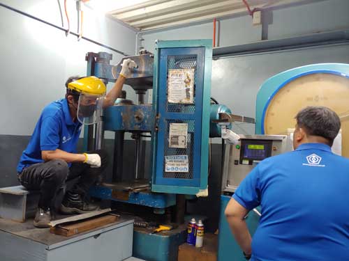
The prepared concrete specimens are placed in a compression testing machine, which applies a progressively increasing load to the specimen. Equipped with load cells and a digital display, the machine accurately measures the applied force.


Loading Procedure:

The test commences with a pre-loading phase, during which a small load is applied to eliminate any irregularities or gaps between the specimen and the testing machine. Subsequently, the main loading phase ensues, gradually increasing the load at a specified rate until the concrete sample reaches failure.


Failure Criteria:
Failure of the concrete specimen is determined when it can no longer withstand the increasing load, causing the measured resistance to decrease. The maximum load the sample sustained before failure occurs is recorded as the compressive strength of the concrete.