1.0 OBJECTIVES
This paper is a review of the historical evolution of Electrokinetics to what it is today, a viable and effective technology for the remediation or treatment of pollutants in-situ and ex-situ. By far, Electrokinetics is one of the most cost effective treatment processes for numerous hazardous materials both organic and inorganic.
The objectives of this review are as follows:
- To provide for a better understanding of the Electrokinetic process, its mechanisms including its advantages and limitations in one single paper.
- To provide for a better understanding of its applicability with various ground contaminations and pollutants.
- To gain a better understanding of how the Electrokinetic process can be further enhanced individually or in combination with other processes such as Hybrid systems.
- To understand the interplay of Soil type, electrochemistry, materials, chemical additives, enhancers and REDOX reactions that drive the Electrokinetic process.
- To determine areas for further research which further improve the process.
While the Review does not claim to provide for a very thorough or complete and authoritative report on the state of practice or the state of the Art, it is hoped that this work can be used as a starting or “ jumping off” point by the readers to gain at least a basic or fundamental understanding of the Electrokinetic process and move onwards. Work in this topic is Dynamic and various sources in the Internet can add to and update the body of knowledge already presented herein to augment research in this field.
2.0 INTRODUCTION
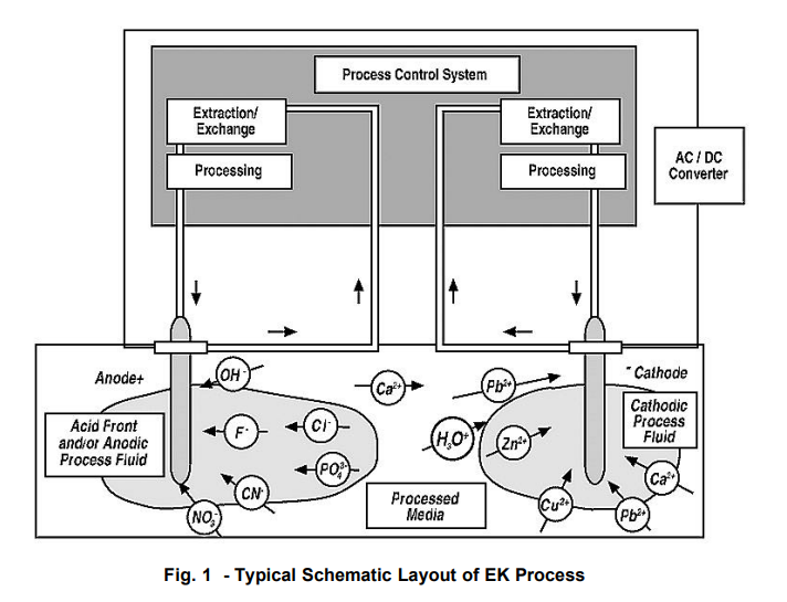
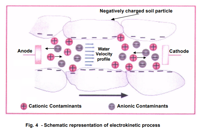
Electrokinetics (EK) is a process that separates and extracts heavy metals, radionuclides, and organic contaminants from saturated or unsaturated soils, sludge, and sediments. A low intensity direct current is applied across electrode pairs that have been implanted in the ground on each side of the contaminated soil mass. The electrical current causes Electroosmosis and ion migration (electromigration) and Electrophoresis, which move the aqueous phase contaminants in the subsurface from one electrode to the other. Contaminants in the aqueous phase or contaminants desorbed from the soil surface are transported towards respective electrodes depending on their charge.
The contaminants may then be extracted to a recovery system or deposited at the electrode. Surfactants and complexing agents can be used to increase solubility and assist in the movement of the contaminant. Also, reagents may be introduced at the electrodes to enhance contaminant removal rates [EPA].
The term “electrokinetics” (EK) refers to the introduction of an electrical gradient (as opposed to a hydraulic or pressure gradient) in the soil to mobilize or promote the migration of water and/or various chemical species towards the preferred electrode.
The procedure takes advantage of the electrically charged characteristics of the soil, its contaminants, the pH as well as the water. In the case of water, the bipolar orientation of the H2O molecule and its preferred orientation in the double layer enhance electrokinetic migration to the electrodes. In the process, breakdown products through hydrolysis of water are formed. The main EK mechanism in such a case is Electroosmosis and this phenomenon can occur whether the soil is coarse- grained sands or fine-grained clays.
In the case of chemical species in the subsurface, various mechanisms interact to promote movement or migration, but generally when these species are in ionic form in suspension.
Electrokinetics (EK) as a soil remediation technology is relatively young, having become an alternative procedure for the removal of toxic chemical species in ionic form in the soil (Lageman, R., Pool, W and Seffinga, G., 1989) in the late 1980’s.1]
Electrokinetics is based on the principle that when direct current (DC) is passed through contaminated soil, certain (negatively charged) types of contaminants will migrate through the soil pore water to a place where they can be removed.
The Electrokinetic Remediation (ER) process removes metals and organic contaminants from low permeability soil, mud, sludge, and marine dredging. ER uses electrochemical and electrokinetic processes to desorb, and then remove, metals and polar organics. This in situ soil processing technology is primarily a separation and removal technique for extracting contaminants from soils. [FRTR]
The demand for an alternative technology to replace costly “remove and treat” processes spurred the clamor for in-situ soil remediation as a cost effective method. This became popular, because of the need for “cleaner” technologies in the 1990’s. (Lageman, et. al. 1989) 1]
Numerous researches and field studies as well as practical applications have brought EK to the status of a practical and cost effective technology for the treatment of contaminated soils. However, much still has to be done to understand the mechanisms as a way to optimizing the processes involved as well as to address other issues to increase the efficiency of the Electrokinetic Process.
A typical schematic layout of the EK process is taken from Pack:
Much of the work gathered for this paper came from various published papers and from the “3rd Symposium and Status Report on Electrokinetic Remediation” (EREM 2001) sponsored by AGK (Angewandte Geologie Karlsruhe) Universitat Karlsruhe and the author’s additional sources such as the USEPA, GWRTC Website, and other Soil remediation websites
The author is particularly very thankful to Dr. Kurt Czurda and Mr. Roman Zorn for providing information on current researches and instrumentation set ups during the author’s brief stay at Universitat Karsruhe and to Dr. Dennes Bergado and Dr. Ulrich Glawe for their guidance and assistance in the preparation of this report.
3.0 HISTORICAL BACKGROUND
In 1808, Reuss observed the electrokinetic phenomena when a DC current was applied to a clay-water mixture. Water moved through the capillary towards the cathode under the electric field. When the electric potential was removed, the flow of water immediately stopped. Napier (1846) distinguished electroosmosis from electrolysis, and in 1861, Quincke found the electric potential difference through a membrane resulted from streaming potential.
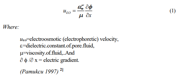
Helmholtz first treated electroosmotic phenomena analytically in 1879. A mathematical basis was provided. Pellat (1904) and Smoluchowski (1921) later modified it to apply to electrophoretic velocity. Out of this treatise of the subject the well known Helmholtz-Smoluchowski (H-S) theory was developed. The H-S theory deals with electroosmotic/electrophoretic velocity of a fluid of certain viscosity and dielectric constant through a surface-charged porous medium of zeta potential (), under an electric gradient. The H-S equation is as follows:
Cassagrande’s studies in stabilizing clays by Electroosmosis started in the early 1930’s. The introduction of an electrical gradient into the soil to stabilize it mainly by removal of the water has its beginnings 70 years ago.
Most of the studies during this early period were directed towards removal of water for soil stabilization and were generally concentrated on the dewatering of fine gravel soils by Electroosmosis. Research on this specific aspect is still continuing with the use of electro conductive elements on PVD drains, which are subjected to an electrical field.
Several Russian researchers used electromigration in prospecting for metals in the 1960’s. The early 1980’s showed marked interest in the exploration of EK Technologies for the removal of toxic chemical species in ionic form in the soil in Europe and the US. Lageman, Pool and Seffinga (1989) 1]
During this period, not all the mechanisms and electrochemical processes were fully understood, particularly insofar as the contribution of the cation exchange capacity of the soil (CEC) to the overall effectiveness of the EK Process. In addition, the various mechanisms have not yet been fully exploited.
Lageman, Pool and Seffinga (1989) 1] focused on the contribution of electromigration and patented the use of circulating electrolytes and the use of ion permeable wells to manage the Anolyte and catholyte. This encouraged further research resulting in the first commercial and successful application of in-situ electro remediation carried out by Geokinetics at the site of a wood impregnation plant to remove Arsenic (As).
This successful application encouraged further researches and field studies resulting in breakthroughs in the understanding of the various processes in EK for in-situ remediation of contaminated soils. While most of the early researches and field studies concentrated on the removal of inorganic pollutants in the soil, more particularly heavy metals, subsequent work were also done on organic pollutants (hydrocarbons) as existing technologies for removal of these contaminants were costly or very time consuming and sometimes stretched out for years instead of days or months. Today, research, field tests and actual applications have shown a dramatic increase as a result of various successes and also as a result of a clearer understanding of EK processes and how these can be further enhanced.
Further research is needed in hybrid systems as well as in making the EK process cost effective particularly directed towards reduction in electrical consumption and the quest for cheaper and more effective electrodes.
4.0 THE EK PROCESS AND ITS MECHANISMS
4.1 FUNDAMENTALS
Although EK can be applied to both coarse and fine grained soils, in the case of the former, the full potential of EK can not be completely mobilized and the beneficial effect is only confined to removal of water as in soil stabilization or preconsolidation. This is due to the absence of a double layer (the “Debye Layer”) in the soil structure as grain sizes are relatively large, thus, preventing the setup of electrical surface charges. These surface charges play a critical role in the remediation of fine-grained soils using electrokinetics EK Procedures.
In order to gain a full understanding of this phenomenon, we would have to review the soil microstructure and the presence of the double layer in fine-grained or Clay soil. The electrochemical processes induced by the introduction of an electrical field in the clay soil results in triggering various mechanisms, all promoting the mobilization of ionic contaminants as well as altering electrical charges in the soil. In addition, redox reactions take place in the electrolytes (Anolyte and Catholyte), which produces chemical changes that promote or inhibit the furtherance of the desired electrochemical reactions and the overall effectiveness of the EK process.
Basic Soil Mechanics points to the presence of an electrically charged clay soil microstructure with preferred charged orientations. The reason behind this is the occurrence of the clay soil particles as submicroscopic with very large surface area to volume (SA/V) ratio thus making electrochemical forces of attraction very significant.
Because of the dipolar nature of water (H2O), the water is captured as “adsorbed” and “absorbed” layers forming in a very simplistic characterization, what is known as a “double layer”.
Because of the critical importance that the double layer plays in the EK process, a detailed description is necessary for a fuller understanding of EK fundamentals since electrochemical reactions can only happen in electrochemically active interfaces having a double layer structure. Doering, F. and Doering, N. (2001) 3]
As described earlier, due to the submicroscopic size of the individual clay platelet, and its high surface area to volume ratio, the clay platelet is a charged particle with an orientation charge effectively making it an “electrode”.
This charged orientation in turn attracts the dipolar water particles with attractive forces that are significantly very strong near the clay platelet and decreases with increasing distance from it. Distance, in this context, being measured in Angstroms or Nanometers.
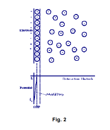
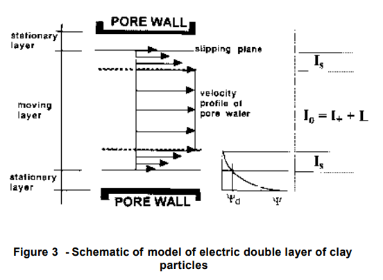
In the figure above, the attracted ions are assumed to approach the electrode surface and form a layer balancing the electrode charge, the distance of approach is assumed to be limited to the radius of the ion and a single sphere of solvation round each ion. The overall result is two layers of charge (the double layer) and a potential drop, which is confined to only this region (termed the outer Helmholtz Plane, OHP) in solution. The result is absolutely analogous to an electrical capacitor, which has two plates of charges separated by some distance (d) [from the “Electrochemistry Refresher” University of Bath].
The H2O molecule configuration allows it to be captured by the charged clay platelet with attractive forces varying inversely with distance from the core. The innermost layer of water is the hygroscopic water corresponding to the Inner Helmboltz Layer (IHL), surrounded by another layer of charged molecules, the solvation water or the Outer Helmboltz Layer (OHL). In between these layers is the Inner Helmholtz Plane (IHP). The transition layer between the IHL and the OHL is the transition layer to the main solution known as the diffuse layer. The next interface, between the diffuse layer and the OHL is the Outer Helmholtz Plane (OHP) where most of the electrochemical reactions take place. Doering, F. and Doering, N. (2001) 3]
Because of the charged orientation in this double layer, the individual clay structure is analogous to an electrode with polarization occurring naturally.
(Pamukcu 1997) 2]
Various researchers have found out, that natural electric fields occur in soil in nature and Schlumberger coined this as “spontaneous polarization”. Doering, F. and Doering, N. (2001) 3]
This Spontaneous Polarization is brought about in natural soils due to the contribution of primary and secondary weathering products of rocks and various minerals. These weathering products essentially consist of metallic minerals such as Iron, Magnesium, manganese or Titanium compounds, carbonaceous materials and humic substances which possess electroconductive properties of varying degrees or intensity.
In Combination with the porewater, these leached out minerals and carbonates as well as other substances provide a clear electric path for the passage of current into the soil. It is this inherent electroconductive property of the combined soil water system, which contributes to the effectiveness of the EK process.
In turn, artificially introducing a direct DC or alternating voltage AC into the soil can further increase electrical fields. It has been found out that these Induced Polarizations (IP) can and do affect silicates, clays and other soil minerals in addition to rocks and metallic ores. (Doering, F. and Doering, N.) 3]
Electrochemical Remediation Technique (ECRT) was a natural follow-on to induced polarization techniques. The main difference being that ECRT required continuous uninterrupted application of DC current for a relatively longer period of time. The induced polarization is brought about by the introduction of physical electrodes into the soil, which causes the set up of a voltage gradient in the soil. However, the individual soil particles possessing Spontaneous Polarization (SP) and IP brought about by EK serves to increase the degree of polarization further. This IP effect causes the set up of oxidation and reduction (redox) processes in each of the individual clay particles or double layer structure.
Induced polarization (IP) causes ions to diffuse to or from the interface resulting in capture or release. The phenomenon is more complex than this; suffice it to say that IP causes changes in the electrical field that induces electrochemical reactions (redox) to occur. Doering, F. and Doering, N. (2001) 3]
Doering and Doering 3] identify the three sources of energy that sustain the electrochemical reactions. These are:
- Spontaneous or provoked polarization occurring naturally in soils.
- The DC fed into the soil by artific ial means.
- Secondary current resulting from soil discharges by the double layer when further excited by an induced electric field.
A voltage range defines the distinction between electrochemical remediation process (ECRT) (where electrochemical synthesis and geo oxidation occurs) and electrokinetics EK or geokinetics (where mobilization of ionic species and mass transport occurs).
Whereas ECRT needs “low current density” applications to initiate electrochemical synthesis at low conductivity ranges of R=0.2 Ω to 10 Ω , higher current densities would be required in the range of R=0.2 Ω to > 40 Ω , in order to initiate mass transport.
At this range, which is the electrokinetic EK application field, immobile heavy metallic compounds can be electrochemically converted into compounds, which could be mobilized. Doering, F. and Doering, N. (2001) 3]
Doering and Doering 3] suggests the name for this process as “induced complexation” (IC) since the chemical transformation mainly covers the conversion of immobile heavy metal compounds into complexations which could be mobilized.
In the electrochemical cell, oxidation and reduction reactions take place at the anode and cathode respectively. These redox reactions take place at every soil interface resulting in electrolysis of the water. The electrolysis produces the oxidizing agent O2 and H2. This Electrochemical Geo-oxidation that results can successfully treat almost all organic pollutants. Doering, F. and Doering, N (2001) 3]
Electrokinetic remediation techniques use low voltage DC on the order of mA/cm2 of cross-sectional area between the electrodes or an electric potential difference on the order of a few volts per cm across electrodes placed in the ground in an open flow arrangement. The groundwater in the boreholes or an external supplied fluid is used as the conductive medium. Open flow arrangement at the electrodes allows ingress and egress of the processing fluid or of the pore fluid into and out of the porous medium. The low-level DC results in physico-chemical and hydrological changes in the soil mass leading to species transport in the porous media. The species input into the system at the electrodes (either by the electrolysis reactions or through the cycling of the processing fluid) and the species in the pore fluid will be transported across the porous media. This will be done by conduction phenomena in soils under electric voltage gradient fields, towards respective electrodes depending on their charge. Non-ionic species will be transported along with the electroosmosis-induced water flow. This transport, coupled with sorption, precipitation and dissolution reactions, comprise the fundamental mechanisms affecting the electrokinetic remediation process.
Extraction and removal are accomplished by several means including electrodeposition (electroplating at the electrode), precipitation or co-precipitation at the electrode, pumping of water near the electrode, or complexing with ion exchange resins Electrokinetics, Inc. (1994). Adsorption into the electrode may also be feasible because some ionic species will change valence near the electrode (depending on the soil pH) making them more likely to adsorb. Murdoch et. al. (1994) 4]
There are several variations of the basic electrokinetic remediation process or implementing strategies:
- Electrokinetic bioremediation (or bioelectric remediation) for continuous treatment of groundwater of soil in situ utilizes either electroosmosis or electrochemical migration to initiate or enhance in situ bioremediation (Bioremediation In Situ Groundwater 18]).
- Electrokinetically deployed oxidation (ElectroChemical GeoOxidation, ECGO19] and Electrochemical Oxidative Remediation of Groundwater 20]).
- Electrokinetically deployed fixation (Fuel Oils, DNAPL’s & Solvents – EH/DPE 21] and Heavy Metals, Arsenic, Cyanide, etc.-Electrokinetic Remediation 22] ).
- Electroheated extraction (Fuel Oils, DNAPL’s & Solvents – EH/DPE 21] ).
- Periodically reversing the polarity of the field is intended to repeatedly pass contaminants through a degradation zone, while limiting the development of high or low pH conditions in the vicinities of electrodes and reducing fouling of electrodes by precipitation. This approach of in situ remediation is the essence of the “Lasagna” process, which will be discussed in detail later in this report.
- Surfactants and complexing agents can be used to increase solubility and assist in the movement of the contaminants.
- Reagents, such as metal catalysts (iron particles, etc.) may be introduced at the electrodes to enhance contaminant removal rates.
4.2 EK Mechanisms
The inherent electro conductive nature of soils particularly moist to wet soils (MC>10%) makes them conducive to EK Processes.
However, other than the spontaneous polarization naturally occurring in soils, the introduction of a direct current by artificial means introduces several mechanisms or phenomena in the soil. These, individually or working together, act to induce mobilization or mobilizes water and other species in solution, whether adsorbed or absorbed in the soil particles.
With the low voltage and low amperage, it is the discharge of electricity from the soil that causes the redox reactions in the soil matrix, in effect; the soil acts as a Capacitor.
The soil–ground water system or the sediment system can be considered as an electrochemical cell. Since the soil particles are already prepolarized by natural electric fields (i.e., spontaneous potential), each soil particle is composed of a part charged positively and a part charged negatively in effect becoming a “microelectrode”. In an electrochemical cell, reactions only occur at the electrodes and comprise anodic oxidation or cathodic reduction.
In soils however, in addition to the local electrode reactions, the complete system of redox-reactions takes place simultaneously at any and all soil particles. These render the soil particles to assume a neutral or nearly neutral pH value. The reaction partners for oxidation and reduction are simultaneously generated at the soil particles by water hydrolysis. Doering, F. and Doering, N. (2001)3]
Empirical evidence indicates that reaction rates are inversely proportional to grain size, such that the ECRTs remediate faster in clays and silts than in sands and gravels
These mechanisms tend to free or release water or chemical species in solution, speed up the transport of pore water or create electrical gradients that induce diffusion or migration of water and other chemical species to the electrodes (Anode or Cathode). In addition, the resulting hydrolysis of water causes significant changes in the pH concentration in the electrodes. The traveling acidic front serves to further aid in releasing the adsorb ions in the soil further increasing the mobilizing effect.
Higher pH (Basic or Alkaline Solutions) is produced at the Cathode end and (the opposite condition) very low-to-low pH is generated at the anode.
The changes in pH at the electrodes tend to either enhance or degrade the effectiveness of the EK process depending on the contaminant specie being mobilized or immobilized. In the case of metals, precipitation may occur in the cathode, which would generally tend to reduce its electroconductivity but at the same time also enhance capture of metals by electroplating the cathode.
Thus, the addition of facilitating agents may or may not be required depending on the remediation objective. This will be discussed later.
The introduction of a Direct Current (DC) in the soil initiates the following phenomena:
- Electroosmosis
- Electromigration
- Electrophoresis
The Diagram below taken from Pack show the foregoing EK induced processes:
4.2.1 Electroosmosis
Electroosmosis is the movement of liquid containing ions relative to a stationary charged surface. The motion is that of a liquid through a membrane (or plug or capillary) as a consequence of the application of an electric field across the membrane. Non-ionic species, both inorganic and organic, will also be transported along with the Electroosmosis induced water flow.
When an electric field is induced in a free draining or normally free draining soil even in the absence of initial pore pressure or hydraulic gradient, pore pressures developed in the soil due to the presence of nonuniformities in the local electric field intensity and or surface electrochemistry.
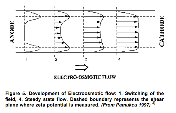
The electroosmotic phenomenon is caused by the accumulation of a net electric charge on the solid’s surface that is in contact with an electrolyte solution and the accumulation of counter ions in a thin liquid (double or Debye) layer next to the solid’s surface. Away from the solid’s surface, the electrolyte is neutral. In the presence of an external (driving) electric field, the counter ions in the Debye layer are attracted to the oppositely charged electrode and drag the liquid along. In other words, the electric field, through its effect on the counter ions, creates a body force that, in turn, induces fluid motion. The electric field intensity and surface (Zeta) potential are the driving parameters for Electroosmosis in a soil region.
When these non-uniform parameters vary in space, there is a non-uniform driving force [local fluid momentum] that must be balanced by a decrease or increase in local pore pressure. This can happen when the net pressure drop is zero and when there is no consolidation of the porous media. The magnitude of the pressure increases with increasing spatial non-uniformity in the driving force and with decreasing hydraulic conductivity.
Pamukcu (1997I 2] illustrated the Spiegler friction model (1958) and showed that electroosmotic water transport per unit electrical charge increases with increasing cation/water ratio in the system. Experimental evidence of this theory has been given by a number of researchers in past (Gray and Mitchell, 1967). An extension of H-S theory considers a portion of the electric current transported near the surface of or through the solid phase (Wiedemann, 1856). The resulting equation is often referred to as the current efficiency, time rate of volume of water flow per quantity of electricity, of the system:
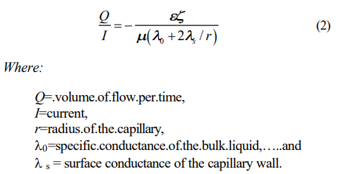
Surface current is due to the ionic motion in the diffuse layer. In narrow capillaries with low ionic concentrations, thus thick diffuse layers, a disproportionate fraction of the current flows in this layer due to the low conductivity of the bulk fluid. Experimental evidence shows that current efficiency, Q/I, decreases with increasing ionic concentration in the bulk fluid (Wittle and Pamukcu, 1992).5] This can be explained readily from Equation (2) since and /are expected to decrease, and 0 to increase with increasing ionic concentration of the bulk fluid. The surface conductance also changes with ionic concentration. As the ionic concentration in the bulk liquid increases, the diffuse double layer shrinks toward the particle surface and the shear plane shifts away from the particle surface so that the majority of the charge is now compensated by the immobile Helmholtz layer. Therefore the charge density in the diffuse layer decreases giving rise to a lower surface conductivity, s. As a result of this lowered conductivity, a smaller portion of the current flows on the capillary surface. In contrast, in the presence of low ionic concentration, the diffuse double layer is swollen and much of the charge is compensated by the ions in the diffuse layer. Therefore, the capillary surface conductivity is high and so is the fraction of the current that is transported on the surface.
The significance of surface conductance in the prediction of electroosmotic flow as it relates to contaminant migration was investigated by Khan (1991). He proposed a modified theory of electroosmotic velocity of water through soil. In this theory, the ‘true electroosmotic’ flow is directly proportional to the current carried by the charged solid surfaces in soil. The soil is modeled as parallel resistances of the soil surface and pore fluid, and the zeta potential used in H-S theory is replaced by the surface potential, d, at the OHP (Outer Helmholtz Plane):
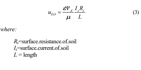
With uEO/Is shown to remain fairly constant for clays of different surface conductivity and also pore fluid electrolyte concentrations below 10-2 M, experimentally, equation (3) was further reduced to the following,
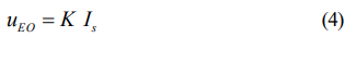
The modified theory basically emphasized that the surface conductivity of the porous compact medium is the most essential precondition for electroosmotic water flow, thus uncoupling it from the water drag component of the migrating ions in pore fluid of high ionic concentration. This theory is in agreement with Spiegler’s theory of water /cation ratio, as well as Gray and Mitchell (1967) approach of co-ion exclusion principle based on Donnan theory of membrane equilibrium (1924). Additional evidence to support this finding was presented by Pamukcu and Wittle (1992) 5] for a variety of ion species, where the ionic concentration effect on the measured current efficiency appeared to be most pronounced in clays with high anion retention capacity. At the same concentrations of dilute solutions of electrolytes, kaolinite clay with higher anion retention capacity (poor co-ion exclusion) showed consistently higher electroosmotic flow than montmorillonite clay with lower anion retention capacity (good co-ion exclusion). This observation suggested that the anionic dragging of water toward the anode diminished the net flow toward the cathode compartment in the montmorillonite clay. (Pamukcu 1997) 2]
Esrig showed that excess pore pressures (negative or positive) could be developed in an incompressible material during Electroosmosis if the voltage drop is non- linear even if the boundaries are freely drained.
Mise suggested that high negative pore pressures measured in free draining kaolinite were due to an imbalance in pH distribution in the soil.
4.2.2 Electromigration
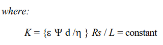
Electromigration defines the movement of ions and ion complexes across the porous media. This occurs via conduction phenomena in soils under electric fields. The average mobility of the ions is approximately ten times greater than that of electroosmotic ability. Lageman, Pool and Seffinga (1989). 1] In electromigration, charged particles are transported through the substrate due to the presence of an electric gradient. The induced Movement resulting from electromigration is superimposed or coupled to the movement induced by Electroosmosis thus further complementing each other.
Pamukcu (1997)2] described Electromigration or ion- migration as the primary mechanism of electro remediation when the contaminants are ionic or surface charged. Speciation and precipitation are major factors in mobilization and transport of heavy metal constituents by ion-migration component of electrokinetics. The speciation is dependent upon a number of fairly well understood parameters including pH, redox potential, and ion concentration. These same factors influence the equilibrium conditions relating to both the soil and the contaminants.
Charged ions moving toward the oppositely charged electrode relative to solution is called electromigration. In a dilute system or a porous medium with moderately concentrated aqueous solution of electrolytes, electro- migration of ions is the major cause of current conduction. Electromigration velocity measures ion movement in the pore water caused by electric field at infinite dilute solutions:
The direction and rate of movement of ionic specie will depend on its charge, both in magnitude and polarity.
Ions and polar molecules in the pore fluid migrate under an electric field. Under the electric field, cations (metal ions) move to the cathodes whereas anions move to anode at different mobilities influenced by the electric charge and physicochemical properties.(Pamukcu 1997) 2]
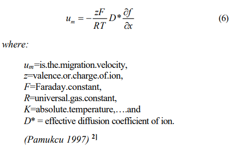
One of the more important aspects of electrokinetic soil processing is the migration of an acid front from the anode to the cathode during the treatment. When electrolysis of water takes place in the surface of electrode, hydrogen ions are produced at the anode and hydroxyl ions at the cathode.
At the electrodes, Electrolysis of water takes place as follows:
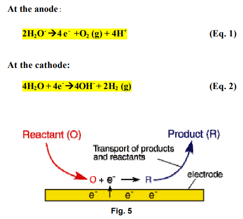
This electrolysis results in an acid front at the anode and an alkaline front at the cathode, respectively. The propagation of the acid and the base fronts promote the dissolution of metal ions near the anode and the precipitation of the metal ions near the Cathode. These conditions significantly affect the pH and ionic strength of pore water, the mobility and solubility of metal contaminants, and charge conditions of soil particles.
The variation of pH conditions in soils by electrolysis of water in the electrode compartment affects ionic strength of pore water and soil surface properties such as cation exchange capacity, magnitude and sign of the electrokinetic zeta potential.
Furthermore, speciation, mobility and solubility of contaminants are often varied with pH in soils during treatment, which may limit or enhance the treatment efficiencies.
Since electromigration is the movement of ionic contaminants and pore water towards the electrodes under electric field without convective movement, it is independent of the Permeability of soils and enables the removal of contaminants from all types of soil.
However, electromigration removes only ionic contaminants such as metal ions dissolved by organic acids and bases.
Electromigration is the key mechanism in removing inorganic contaminants, especially metal ions. (Kim, 1998).
4.2.3 Electrophoresis
Electrophoresis is the transport of charged colloids or solid particles under applied direct current DC electric field towards the electrodes as a result of their orientation with the electric field. Electrophoresis acts oppositely of Electroosmosis as the charge particle moves relative to a stationary fluid.
Charged particles including microorganisms (bacteria) may be affected by two processes: EO encourages the movement of the cells towards the cathode while EP will move negatively charged cells towards the anode. Movement is therefore determined by the surface charge characteristics of the Bacteria strain and the direction of bacteria movement is manipulated by altering the electrical field. (Oxford University CE Publication on the Web).
In a compact system of porous plug, electrophoresis should be of less importance since the solid phase is restrained from movement. In some cases, however, electrophoresis of clay colloids may play a role in decontamination if the migrating colloids have the chemical species of interest adsorbed on them. An important contribution of electrophoretic movement to
contaminant transport may be when the contaminants are in the form of colloidal electrolytes or ionic micelles.
Colloids are made up of ionizable groups attached to large organic molecules, macromolecules, and aggregates of ions. Ionic micelles or colloidal electrolytes also develop electric double layers about themselves. If the particle conductivity is the same as the surrounding liquid and the electrokinetic potential is low (< 25 mV), then the particle mobility can be described by the Smoluchowski equation. For larger values of electrokinetic potential the effects of electrophoretic retardation and relaxation should be considered, similar to the consideration in electrolyte solution. (Pamucku and Wittle, 1992) 5]
4.3 Factors Affecting Electrokinetic Technology
4.3.1 General
Electromigration rates in the subsurface depend upon grain size, ionic mobility, contamination concentration, total ionic concentration, and significantly upon the soil pore water current density and pH. The process efficiency is not as dependent on the fluid permeability of soil as it is on the pore water electrical conductivity and path length through the soil, both of which are a function of the soil moisture content (Wallmann, P.C. 1994) 6]
The direction and quantity of the contaminant movement is influenced by the contaminant concentration (anions versus cations), soil type and structure, pH, interfacial chemistry, and current density of the soil pore water. Electrokinetic remediation is possible in saturated and unsaturated soils. Experimental results indicate that there is a minimum moisture content at which electromigration can take place, which is related to, and can be estimated from, the residual moisture content of a soil, also called “immobile water.” The soil moisture content must be high enough to allow electromigration, but for optimum results, should likely be less than saturation, to avoid the competing effects of tortuosity and pore water content. The direction and rate of movement of an ionic species will depend on its charge, both in magnitude and polarity, as well as the magnitude of the electroosmosis-induced flow velocity. When electroosmosis processes are operative, non-ionic species will be transported along with the induced water flow (Wallmann, P.C. 1994) 6]
The efficiency of extraction relies upon several factors such as the type of species, their solubility in the specific soil, their electrical charge, their concentration relative to other species, their location and form in the soil, and availability of organic matter in the soil. (Electrokinetics, Inc. 1994 23] and LasagnaTM Public-Private Partnership, 1996 24]).
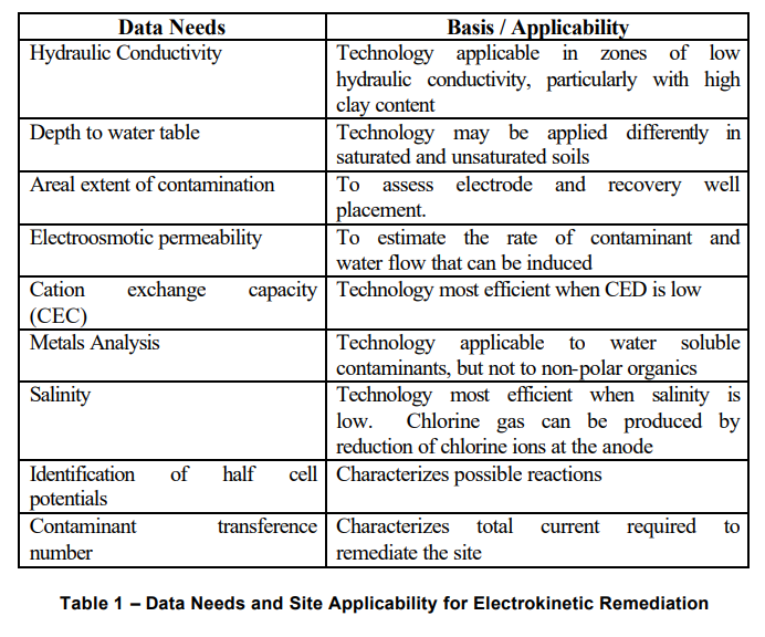
Electrokinetics is applicable in zones of low hydraulic conductivity, particularly with high clay content. The technology is most efficient when the Cation Exchange Capacity (CEC) and the salinity are low.
During electrokinetic treatment, electrolysis results in the formation of H+ and OH-. These migrate toward one another by electrokinetic processes. As these two fronts meet, a rapid transition from low to high pH occurs, creating a region of minimum solubility of metals. These sharp discontinuities in pH induced within the soil mass by electrokinetics could result in a deposition front where minerals are precipitated in soil pores, markedly reducing permeability and inhibiting recovery. This can be prevented by flushing the cathode with water or a dilute acid to arrest the migration of the OH- front into the soil (Cox, et al 1996) 7]
4.3.2 Data Needs and Site Applicability
The EK technology can be deployed in one of the following ways (Geokinetics 1997):
- In-situ Remediation- Electrodes are placed directly in the ground and contamination is recovered with minimal disturbance to the site.
- Batch Operation- Contaminated media is transported to a batch facility and treated ex- situ.
- EK Ring Fence- a chain of electrodes is deployed in-situ to recover ionic contamination from groundwater as it flows past the electrodes.
- Use with PEREBAR- EK when used with Permeable Reactive Barriers can enhance the removal efficiency of the PEREBAR by selectively removing contaminants or chemical species, which could otherwise precipitate or clog the reactive barriers.
The Table below taken from ITRC Website lists the data requirements needed to determine applicability of the EK process:
4.3.3 Enhancing the EK Process
In some instances, it would be desirable to enhance the process with the use of water, bio nutrients, surfactants, additives and ion exchange columns and reactive barriers etc., as well as Electrodialytic processes in order to enhance the desired results. Several experiments in the laboratory as well as in the field have been performed for this purpose.
USE of SURFACTANTS
Surfactants are used in order to “condition” or enhance the solubility and mobility of organics in the soil. In a research described by Mansour, et. al., a Hybrid experiment was conducted combining the use of conditioning agents, ion exchange textiles and chelating agents in combination with EK.
In this hybrid experiment, the target contaminants are Lead (Pb), Nickel (Ni) and Phenantrene, which is a polyaromatic Hydrocarbon (PAH). Water is added at the anodic well continuously throughout the experiment and surfactant was added continuously at certain stages also at the anode side. The chelating agent EDTA was added at the Cathode end.
The results of this experiment showed that where the surfactant as well as the EDTA was added, the recovery rate was highest which was in a cell (C6).
The removal rates were remarkable as follows:
- Lead Pb 85 %
- Nickel Ni 84%
- Phenantrene 74%
It was also shown in the experiments that:
- Use of EDTA decreased the electrical resistance of the soil.
- Sequenced Application of EDTA and then the surfactant was the most effective procedure.
- Introduction of the surfactant at the onset of the test increased the soil’s electrical resistance.
USE of BIOSURFACTANTS
In another experiment conducted by Electorowicz, et. al. (1994)8] biosurfactants were used in order to increase the solubility of PAH’s into the aqueous phase from clayey soil without the introduction of hazardous contaminants.
Biosurfactants are introduced into the soil in order to solubilize the organics from the soil and cause it’s desorption. Bacteria tend to increase the solubilization of organic compounds, which in turn are attacked, by the bacteria for its metabolism. Bacteria produce rhamnolipids and fatty acids, called Biosurfactants that change the surface tension of the pore liquid and form micelles with organic contaminants (Francy, et. al. 1991). 9]
These micelles exhibit increased “bioavailability” and are more easily transported through the soil. However, the natural production of Biosurfactants in clay is very limited (Electorowicz 1999), 8] thus a means of introducing additional biosurfactants into the soil through external means would be highly desirable to increase the bioavailability and attack of organic compounds. It was thought that the negatively charged biosurfactants could be transported through the clayey soils through electrokinetics means.
The ensuing experiment (Electorowicz et. al. 1994) 8] showed the effectiveness of the addition of biosurfactants to enhance the mobility and solubility of the Phenantrene and its successful removal to about 80% level in the soil.
USE with PEREBAR
Permeable Reactive Barriers (PEREBAR) have been used independently before to intercept contaminated Groundwater flow in order for the Contaminated groundwater to flow through the permeable barrier material. The reactive barrier usually consists of granulated iron particles. In the process, the elemental iron (Fe) acts as a reducing agent, which reacts with chlorinated hydrocarbons. The redox reaction with iron generates a ferrous ion and two electrons are freed in the process.
Chemical reduction using iron is applicable to the removal of heavy metals.
However, in most instances, fouling up or clogging of the reactive barriers happen, rendering it inefficient due to formation of precipitates.
In order to remedy this, EK is introduced upstream of the PEREBAR in order to reduce the amount of groundwater contaminants and also by increasing the mobility of the groundwater through fine grained soils by the presence of an Electric gradient and activating the EK mechanisms EO, EP and EM to occur.
Thus, the overall process is enhanced with the introduction of EK techniques.
5.0 THE EFFECT OF pH on the PROCESS
5.1 Water Hydrolysis
When electric current is passed through a solution, the hydrolysis of water is initiated. This results in half reactions to occur at the electrodes (either oxidation or reduction) resulting in a change in pH. (Lageman et.al. 1989) 1]
However, in the soil particles, full redox reactions take place resulting in a neutral pH level once the full redox reactions take place.
The electrolysis reactions, caused by the electric current passing through the soil and solution, occurring at the electrodes generate an acidic medium at the anode and an alkaline medium at the Cathode. The H+ ion generated at the anode advances through the soil towards the Cathode by electromigration, electroosmosis and electrophoresis.
The rate of migration from the Anode to the Cathode is slowed down through the soil and therefore more rapid localized evolution of acids and bases at the Anolyte and Catholyte occur in time with the process. This generates high pH values (alkaline) at the Cathode and low pH values (Acidic) at the Anode. Generally, H+ exhibit a higher affinity to the soil than heavy metal ions, thus metal ions are exchanged by the soil with the H+ ion thereby releasing metals in solution which can travel through EK induced mechanism (ACAR et.al 1993). 10]
The reduction reaction at the Cathode (Jy, et.al.) zone hydrolyses water to form H2 and OH- during electrolytic dissociation. The H+ and OH- ions generated from the electrolytic dissociation are moved across the fluid within particles toward either anode or cathode (Reed 1998). 11]
Because of the electrical gradient induced by the passage of current through the electrodes, the Hydronium ion (H30+) evolved in the anode advances towards the Cathode. This results in the advance of an acidic front. Likewise, hydroxyl ions OH- are generated at the Cathode, which migrates towards the anode as a front. An abrupt change in the pH results when these two fronts collide.
The Acid front moves faster than the Basic front because of the higher mobility of the H+ compared to the OH- and because the direction of electroosmotic flow is towards the Cathode. After a while, the soil becomes generally more Acidic throughout its volume except very near the Cathode influence zone except when the soil is buffered or generally Alkaline or if Reactive electrodes inhibit the acidification of the Anolyte. (Page and Page, 2002)12]
When the two fronts collide within the soil mass, water is formed and a sharp change in pH is experienced which affects the solubility and adsorption of the contaminants. (Page and Page, 2002). 12]
In the case of the use of inert (as opposed to reactive metal) electrodes, pH tends to increase in the electrodes and decrease in the anodes.
However, when reactive metal electrodes are used in the anode and as observed by Doering, the steel in the anode is serving as a sacrificial anode and is subject to oxidation and water electrolysis. Water electrolysis unsuccessfully competes with the oxidation of the steel. Thus, electrolysis is stopped and pH change does not occur at the anode.
On the other hand, the use of steel electrodes for the cathode
allows electrolysis to occur resulting in an increase in pH.
As will be discussed later, the choice of electrodes and pH control would be important considerations in the conduct of the EK Remediation.
5.2 Generation of the Acid Front
Generation and significant changes in the pH brought about by electrolysis of water significantly affects the contaminant removal process. Because of its faster rate of propagation or travel relative to the Basic front through the soil, the acid front affects the surface charge characteristics of the clays cation retention capacity (CEC).
This creates temporarily a highly acidic condition generally which serves to desorbs metal species in the soil.
The CEC of the clay decrease in a low pH environment and create suitable environments for the metal ions to remain in solution (desorption) in the bulk pore liquid so that they can be extracted more easily (Ricart et.al. 2001). 13] However, the generation of OH- in the Cathode increases the likelihood of precipitation of ionic species, reducing the efficiency of the Cathode and the electrokinetic process in general.
The pH condition may affect different metals in different ways; metal cations such as Zn2+ and oxy-anions under alkaline conditions (ZNO2 2-) are stable under acidic conditions. (Page and Page, 2002) 12]
This points to the critical importance and attention that needs to be paid to pH generation and its control or non-control during the EK process.
Thus, pH as well as the contaminant type has a greater influence on the removal process rather than electroosmotic flow.
5.3 Effects of pH on Electrode Efficiency
The pH condition at the Electrodes has a marked effect on Electrode efficiencies. As earlier discussed, high conditions occur at the Cathode encouraging precipitation of Carbonates as well as electroplating or deposition of metals on the electrode surface. This precipitation and electroplating both tend to degrade the electroconductivity of the Cathode thus directly affecting the EK process. However, this by itself is not totally objectionable, particularly if the objective is to recover precious metals in suspension (electromining) and if the electrode material is inexpensive and is easily replaceable.
Conditioning of the electrode reservoirs has been used by Reed et al (1995) 11] in order to improve performance.
This condition on pH intervention was demonstrated in an experiment conducted by (Ricart et.al. 2001). 13] On sludge subjected to EK process. The pH in the Cathode was adjusted to 2 with concentrated HN03. This prevented the increase in pH in the sludge being treated and permitted the abundant migration of H+ ions from anode to cathode. This resulted in reduction of the pH in the sludge from 7.3 to 4 in 8 days. The anode pH further dropped down to 1.0. The electrical resistance was significantly reduced and current intensity subsequently was increasing continuously. This was due to the abundance of ions in the sludge, which came from the H+ ions and elements dissolved from the sludge.
In general, extraction efficiency or dissolution of metals from mineral solids is enhanced significantly by acid attack advancing through the soil in addition to the corollary increase in current intensity and acid reduction in electrical resistance which could among others work to reduce electricity consumption. A noticeable drop in conductivity has been attributed by (Cambefort and Caron, 1961) as being due to a Sharp pH jump at the region very near the cathode and also due to the precipitation of heavy metal ion contaminants.
5.4 Changing or Maintaining pH Values
Control of pH during the EK process therefore influences the direction of the remediation process in the following ways:
5.4.1 No Control of pH
Allowing the Electrolysis (redox reactions)) to occur without intervention or control of pH results in the generation of acid and basic fronts which eventually collide within the electric field. The soils essentially remain neutral in pH and undergo complete oxidation and reduction processes. The Anolyte becomes very acidic and the Catholyte produces a highly basic solution.
The high pH at the Cathode encourages precipitation of Calcium (Ca) and other heavy metals in the Cathode. This action produces the following results, which may or may not be the desired or objective result:
⦁ Electroplating of the Cathode with metals. (Sometimes desirable as in Electromining)
⦁ Precipitation of calcium and other carbonates in the Cathode region reduces its electroconductivity retarding the EK process and resulting in very high current consumption.
The advancing acidic front in turn (and as earlier indicated) causes the dissolution and desorption of metals and its release into the solution. The acidification of the soils enhances the desorption of the metal from the soil by exchange of metal ion for hydrogen ion.
In some instances, desorption of some metals in the soil is not desirable particularly if these are stable in their original natural state and hence an acid front generated may not be desirable. This is particularly true when only organic pollutant and not stable metal species are targeted for removal.
If the only intended objective in inducing an electric field in the soil is to remove water by an electrical gradient, the rapid advance of the acidic front which causes precipitation at the Cathode can be avoided by “Toggling” or cyclic reversal of polarities between the Anode and the Cathode. Whereas, water is still free to migrate due to the electrical gradient, the acid front is controlled preventing foul up of the Cathode.
5.4.2 pH Control at the Anode
Anolyte – Maintaining the Anolyte pH level to very low values increases the generation of H+ ions thus aggressively generating an advancing acidic front. This is conducive to releasing and recovering metal contaminants from the soil. The abundance of electrons also facilitates electroconductivity and allows current to pass more easily in the field.
On the other hand, the use of a highly reactive metal (steel) in the anode prevents the generation of H+ and thus retards the advance of an acidic front.
This means of controlling the acidic front can be used to immobilize the desorption of metals which are sometimes better left in place allowing only organic pollutants to be removed by EK.
6.0 APPLICATIONS OF THE ELECTROKINETIC PROCESS
6.1 Fields of Application
In his paper, Pamukcu, 1997 2] discussed the research in electrochemical treatment for the purpose of restoring contaminated subsurface which has accelerated in the past two decades. Some of the currently researched methods of electrochemical treatment (Marks et al., 1994, 1995; Ho et al., 1995; Yeung, 1990; Mitchell and Yeung, 1991; Hansen, 1995; Pamukcu et al., 1997; Haran et al., 1995). Have been termed as:
- Electro-kinetic extraction;
- Electro-kinetic barriers;
- Electro-bioremediation;
- Electro-stabilization (injection);
- Electro-containment
Electrokinetics had been used to induce dewatering of soils through Electroosmosis. Shang, (2000) 14] conducted Laboratory Tests on mine tailings and also on marine clays. The effectiveness of EK Induced Electroosmosis was clearly apparent in these experiments.
Electrokinetics have also been employed successfully for consolidation of clays by providing electroconductive geosynthetics to induce dewatering through Electroosmosis (Jones, et. al. 2002) 15] (Karunarathe, et. al. 2002) 16]
The electroosmotic water flow was found out to be greater than what would have resulted under normal consolidation methods. This consolidation was also accompanied by significant increases in shear strength of the treated zone.
The earlier work focused on utilizing the technique for soil densification as an aid in containment facilities Later, others studied the effects of electrolysis on soil chemistry and the use of electrokinetics to contaminant removal from soil The feasibility and cost effectiveness of the contaminant extraction technique have been demonstrated through numerous laboratory studies and some pilot scale studies.
Banarjee and co-workers (1987) published a field feasibility study for the potential application of electrokinetics for chromium removal from subsurface. Acar and coworkers (1989) realized the importance of pH gradients generated from anode through cathode by the process. In the same year, Lageman and co-workers (Lageman et al., 1989) 1] attempted to utilize pH gradient by controlling the chemical environment around the electrodes. Pamukcu et al. (1991) 2] presented the effects of speciation and precipitation on the efficiency of electrokinetic transport of zinc through soil. Other lab studies further substantiated the applicability of the technique to a wide range of contaminants in soils. Among the contaminants which have been shown to react to electrochemical treatment in the laboratory and a few in the field, are non-aqueous phase liquids such as chlorinated hydrocarbons, mononuclear aromatic hydrocarbons (MAHs), polynuclear aromatic hydrocarbons (PAHs), phenols, sulfurous, nitrogenous compounds and, of course, metals. Ho and co-workers (1995) presented an integrated method of soil restoration method that relies on electrochemical technology. Current field demonstration results of this technology, also known as Lasagna; Soil Remediation, are available from US Department of Energy (1996).25]
Past experience with electrochemical treatment of contaminated porous media has shown that the process is most effective when the transported substances are ionic, surface charged or in the form of small micelles with little drag resistance. This is analogous to soil washing whereby the contaminant is extracted from the soil and subsequently collected in aqueous phase in a collection well or deposited at the electrode site. The alkali metals and alkali earth metals such as Na, K, Cs and Sr, Ca tend to remain ionic under a wide range of pH and redox potential values. Therefore they are expected to electromigrate and are extracted from soil readily unless they become preferentially sorbed onto solid surfaces and clay interstices. Under ideal conditions, the predominant cation and its accompanying anion may be caused to separate efficiently by electromigration only, for which little or no electroosmotic water advection may be necessary. Small anions such as chloride and thiosulfate are so mobile that they can migrate toward the anode despite a strong electroosmotic flow toward cathode (Weinberger, 1997). Pamukcu et al. (1991) 2]
When extraction may become ineffective or infeasible, electrochemistry may still be useful to stabilize and/or contain certain groups of metals and some organic compounds in the ground. In conjunction with environmental restoration, stabilization is defined as fixing the toxic substance in place thereby rendering it less likely to move elsewhere under ambient hydro geological conditions. Electrochemical stabilization can be accomplished by delivering an appropriate oxidizing or reducing agent to the contaminant in the soil that subsequently will: (i) degrade the contaminant; or (ii) change it to a non-toxic or immobile species; or (iii) enhance stable sorption and incorporation of the contaminant into the clay minerals. Zero- valent iron enhanced degradation of TCE and Fe (II) degradation of toxic Cr (VI) to less toxic and less mobile Cr (III) are examples of such processes Pamukcu et al. (1991) 2]
Containment may be defined as causing controlled accumulation of the toxic substance by sorption in a small volume of substrate. Electrochemical containment may be accomplished by causing the electro-migration or electroosmotic transport of the contaminants to reactive permeable barriers strategically situated between the electrodes, where they are attenuated and the filtered water is allowed to pass through (Hansen, 1995; Weeks and Pamukcu, 1996). In actual field applications, such permeable structures could be installed at various positions throughout a contaminated site serving as primary and secondary treatment locations. Such structures are referred to as “reactive permeable barriers” (Rael et. al., 1995; Blowes et al., 1995). The basic idea behind these reactive barriers is to allow the flow to advance the contaminant plume through an in-situ structure containing a substance that will react with the contaminant. When a directed flow of contaminants by electroosmosis or electromigration enter a permeable bed of sorbents material situated in the path of the flow, the water may be filtered sufficiently depending on the rate of flow through the bed as well as the attenuation characteristics of the bed. Pamukcu et al. (1991) 2]
6.2 Technology Performances and Case Studies
The Section was directly taken in part from a 1997 State of the Practice report by the GWRTAC (Groundwater Remediation Technologies Analysis Center.) insofar as commercially available technologies are concerned. Additional updates on the emerging technology have been added by the author and embedded into the report to make this relatively more complete or updated.
“Due to the specialized nature of electrokinetic remediation, as well as its innovative status, relatively few commercial vendors apply the technology. Therefore, in this section of the report, several trademarked or patented commercial electrokinetic processes are described, as well as additional extended uses of electrokinetics, such as electrokinetic bioremediation and oxidation, and electro-heating to enhance technologies such as vapor extraction, and others. This information is provided for informational purposes only.”
6.2.1 Electro-KleanTM Electrical Separation
Electro-KleanTM is a process available through Electrokinetics Incorporated of Baton Rouge, Louisiana. The process removes or captures heavy metals, radionuclides, and selected volatile organic contaminants from saturated and unsaturated sands, silts, fine-grained clays, and sediments. It can be applied in situ or ex situ. Electrodes are placed on each side of the contaminated soil mass, and direct current is applied. Conditioning fluids such as suitable acids may be added or circulated at the electrodes to enhance the process electrochemistry. The concurrent mobility of the ions and pore fluid decontaminates the soil mass, as the contaminants migrate to the electrodes. Contaminants are separated on the electrodes or separated in a post-treatment unit (Electrokinetics, Inc.).
Electro-Klean extracts heavy metals, radionuclides, and other inorganic contaminants, and can reduce their concentration to below their solubility limit. Treatment efficiency depends on the specific chemicals, their concentration, and the buffering capacity of the soil. The technique proved 85 to 95% efficient for removing phenol at concentrations of 500 ppm. In addition, the removal efficiency for lead, chromium, cadmium, and uranium at levels up to 2,000 mg/kg, ranged between 75 and 95%.
6.2.2 Electrokinetic Bioremediation
Electrokinetic bioremediation technology is designed to activate dormant microbial populations by use of selected nutrients to promote growth, reproduction, and metabolism of the microorganisms capable of transforming organic contaminants. The bioelectric technology directs the nutrients to the organic pollutant. Normally there is no requirement to add microorganisms (Electrokinetics, Inc.).
The economics of this process are favorable because external microbial populations are not required, and nutrients can be uniformly dispersed over the contaminated volume of soil or directed at a specific location, thus reducing nutrient costs. This process may be extremely valuable because it avoids the problems associated with transport of microorganisms through fine- grained soils.
Electrokinetic bioremediation (or bioelectric remediation) technology for continuous treatment of groundwater or soil in situ utilizes either electroosmosis or electrochemical migration to initiate or enhance in situ bioremediation.
Electroosmosis is the dominant process where a direct current can produce an accelerated flow of groundwater in the soil strata. Electroosmosis flow develops more easily in sands, sandy silts or sandy clays. Biological growth factors, including microbial populations, surfactants, and inorganic and organic nutrients, can be moved and often directed into the soil/groundwater matrix. Electroosmosis in this case can be used to accelerate the natural groundwater movement and increase the efficiency of the biodegradation process by the addition of the biological agent into the coarse soils. The flow in coarse-grained soils, however, will tend to follow natural fissures or high permeability lenses and not be uniform throughout the bed. Thus the possibility exists that organic pollutants present in lower permeability areas may not be remediated.
Electrochemical or ion migration is the dominant process in stiff silty clays and mixed clays. Under these conditions, electroosmosis has limited or no effect on groundwater movement. With electrochemical migration, the electrical field will move more uniformly through the soil and ions will readily pass through the small pores in the clay. Natural biological populations tend to exist around organic pollutant spills in soils. Complex organic compounds, however, are not prime energy sources for microbial populations and biodegradation will not flourish until sufficient food, nutrients, and electron acceptors are available to initiate growth and reduce the organic pollutant concentration. The electrical field in this case spreads charged soluble inorganic and some simple organic nutrients uniformly through the site and directs these nutrients to the spatial locations where the food source (e.g., hydrocarbon pollutant) is located.
Limitations of the process include the following:
- The concentration of the organic pollutant may be above the toxic threshold limit of the microbial population.
- The bioremediation of mixed organic pollutants may produce by-products, which are toxic to the microorganisms, thereby inhibiting the biodegradation process.
6.2.3 Electrochemical GeoOxidation (ECGO)
ElectroChemical GeoOxidation (ECGO) is a patented in situ technology available from ManTech International Corporation (a license of Geotechnologies of Germany) that remediate soil and water contaminated with organic and inorganic compounds. The ECGO in situ works by applying an electrical current to probes driven into the ground. The process utilizes induced electric currents to create oxidation-reduction reactions, which lead to the mineralization of organic constituents (or the immobilization of inorganic constituents) present in a volume of soil and groundwater between the electrode locations (ElectroChemical GeoOxidation, ECGO 19]).
ECGO relies on the induced polarization of naturally occurring conducting surfaces in soil and rock particles. These conducting surfaces are composed of elements such as iron, magnesium, titanium and elemental carbon. Heavy metal impurities that are also naturally occurring further contribute to the process by acting as catalysts for the redox reactions.
Depending on the site conditions, accessibility, and targeted constituents, the ECGO process may take 60 to 120 days.
6.2.4 Electrochemical Oxidative Remediation of Groundwater
Under contract from the Air Force Armstrong Laboratory at Tyndall Air Force Base, SRI International, a non-profit organization with its headquarter in Silicon Valley, California, is developing an innovative technology for groundwater remediation that uses a permeable electrochemical oxidation reactor (PEOR) that is part of an engineered system placed within an aquifer. A stand- alone wall system comprised of porous carbon electrodes and an iron-based catalyst is being designed for installation in the path of a contaminant plume. Utilizing the natural hydraulic gradient, groundwater flows into the permeable wall, where the electrodes are used to generate hydrogen peroxide, which decomposes to hydroxyl radicals in a reaction catalyzed by the iron-based catalyst. The hydroxyl radicals oxidize the organic contaminants in situ, and purified water flows out of the wall into the aquifer. The technology is suited for active pumping or passive groundwater flow. It combines the advantages of an advanced oxidation process with the ability of electrochemical methods to generate oxidants in situ at a controllable rate (Electrochemical Oxidative Remediation of Groundwater, 1997 20]).
6.2.5 Electrochemical Ion Exchange (EIX)
Geokinetics International Incorporated, (GII), a joint venture of five separate companies, uses a combination of electrokinetics and above ground Electrochemical Ion exchangers (EIX’s) to remove ionic contamination from environmental media (Complementary Technologies – Electrochemical Ion eXchange 26] ).
A series of electrodes are placed in porous casings, which are supplied with circulating electrolytes. Ionic contamination is captured in these electrolytes and pumped to the surface where the recovered solution is passed through the electrochemical ion exchanger, which selectively recovers the contaminants allowing the reuse of some of the contaminants.
Because cleaning effluents containing low levels of contamination can be difficult and expensive, EIX can isolate and recover heavy metals, halides, and certain organic species. Typically, inflow concentrations of target species in the range 10 to 500 ppm can be reduced to less than 1 ppm.
Decontamination costs are expected to be in the range of $200 to $325 per cubic meter ($150 to $250 per cubic yard).
6.2.6 ElectrosorbTM
The ElectrosorbTM technology of Isotron Corporation (New Orleans, Louisiana) uses cylindrical electrode assemblies where the electrode is coated with Isotron’s IsolockTM polymer material. The polymer is impregnated with pH-regulating chemicals to prevent fluctuations in pH. The electrodes are placed in boreholes in the soil and a direct current is applied. Under the influence of the current, ions migrate through the pore water to an electrode, where they are trapped in the polymer matrix. If desired, the polymer can also contain ion exchange resins or other sorbents that can trap and hold ions before they reach the electrode. The electrode assemblies and equipment needed for the operation are all commercially available (Department of Energy 1995 27] and ISOTRON Products and Services 1996 28] ).
6.3 LasagnaTM Process
6.3.1 LasagnaTM Public-Private Partnership
In early 1994, the U.S. Environmental Protection Agency (EPA) signed a Cooperative Research and Development Agreement with a private consortium, consisting of Monsanto, DuPont, and General Electric to jointly develop an integrated in situ remedial technology. In early 1995, with significant funding by the Department of Energy (DOE), the work group initiated a field experiment.
General roles of partnership members are (RTDF LasagnaTM Partnership – Remediation Technology Development Forum, 1996 29]):
- DuPont: Anaerobic biodegradation and vertical zone installation;
- General Electric: Electrokinetic and physiochemical treatment;
- Monsanto: LasagnaTM, electroosmosis, Biodegradation;
- DOE: Site selection and field support, and,
- EPA: Hydrofracturing, biodegradation
6.3.2 Technology Description
The LasagnaTM process so named because of its treatment layers combines electroosmosis with treatment zones that are installed directly in the contaminated soils to form an integrated in situ remedial process. Electroosmosis is well known for its effectiveness in moving water uniformly through low-permeability soils at very low power consumption. Electrokinetics is used to move contaminants in soil pore water into vertically or horizontally oriented treatment zones where the contaminants can be captured or decomposed. Conceptually, the LasagnaTM process would be used to treat inorganic and organic contaminants, as well as mixed wastes.
Major features of the technology are (U.S. Department of Energy – LasagnaTM Soil Remediation 1996 25]):
- Electrodes energized by direct current cause water and soluble contaminants to move into or through treatment layers, and heat the soil;
- Treatment zones contain reagents that decompose the soluble organic contaminants or absorb contaminants for immobilization or subsequent removal or disposal;
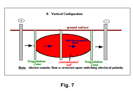
- A water management system recycles the water that accumulates at the cathode (high pH) back to the anode (low pH) for acid-base neutralization. Alternatively, electrode polarity can be periodically reversed to reverse electro-osmotic flow and neutralize pH.
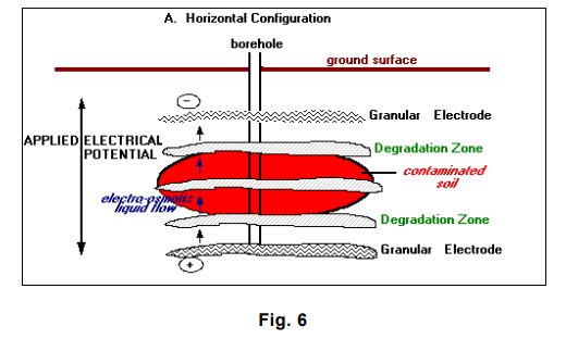
The orientation of the electrodes and the treatment zones depends on the site/contaminant characteristics. In general, a vertical configuration is probably applicable to shallow contamination (within 15 meters [50 feet] of the ground surface), whereas a horizontal configuration, using hydraulic fracturing or related methods, is capable of treating much deeper contamination (U.S. Environmental Protection Agency 1996 – LasagnaTM Public-Private Partnership 24]).
6.3.3 Technology Status
Phase I – Vertical Field Test at the DOE Paducah Gaseous Diffusion Plant (PGDP) in Kentucky focused on in situ TCE (trichloroethylene) remediation. The test operated for 120 days and was completed in May 1995. The zone to be remediated measured 4.5 meters wide by 3 meters across and 4.5 meters deep (15 ft by 10 ft by 15 ft deep). The average contamination was 83.2 ppm, and the highest TCE concentrations (200 to 300 ppm) were found 3.5 to 4.5 meters (12 to 18 feet) below surface.
About 4% of the total TCE was lost through evaporation. Soil samples taken throughout the test site before and after the test indicate a 98% removal of TCE from a tight clay soil (hydraulic conductivity <10-7 cm/sec), with some samples showing greater than 99% removal.
TCE soil levels were reduced from the 100 to 500 ppm range to an average concentration of 1 ppm.
DNAPL (dense non-aqueous phase liquid) locations were cleaned to 1-ppm levels except for a 4.5 meter deep sample that was reduced to 17.4 ppm. Because treatment zones were only 4.5 meters deep, diffusion from untreated deep zones may have contributed to the 17.4 ppm result.
Phase II – Vertical Field Test, also conducted at the DOE PGDP, will modify the Phase I configuration by using zero-valent iron in the treatment zones chemically reduce TCE to non-toxic end products. The zone being remediated measures 6 meters wide by 9 meters across and 13.5 meters deep (20 ft by 30 ft by 45 ft deep). This is approximately 20 times more soil (1,360 tonnes, or 1,500 tons) than was treated in Phase I. Phase II is to help resolve scale-up questions, substantiate technology cost estimates, and evaluate the performance of zero- valent iron in the treatment zones. The test is scheduled to be complete on August 4, 1997.
Various treatment processes are currently being investigated in the laboratory to address other types of contaminants, such as heavy metals and mixed wastes (U.S. Department of Energy – LasagnaTM Soil Remediation 1996 25]):
6.3.4 Process Advantages
- Effective in low permeability soils (hydraulic conductivity <10-5 cm/s)
- Contaminants can be destroyed underground
- Silent operation
- Rapid installation, low profile
- Relatively short treatment duration (RTDF LasagnaTM Partnership – Remediation Technology Development Forum, 1996 29])
6.3.5 Costs
Direct treatment costs of a 0.4 hectare (one-acre) site similar to that used in the Phase I test are estimated at
$105-$120/m3 ($80-$90/yd3) for remediation in one year and at $65-$80/m3 ($50-$60/yd3) of soil if the remediation could occur over a period of three years. Comparable estimates for the Phase II mode of operation are $80-$90/m3 ($60-$70/yd3) for one year, and $50-$60 ($40-$50/yd3) for three years. Deeper contamination, although involving more technically challenging emplacement, costs less because of the larger area of influence per electrode (In Situ Solvent Remediation 30]).
6.3.6 Cost Savings Versus Alternative Technologies
DuPont has benchmarked a number of in situ technologies over the last three years. These include:
- In situ treatment zones using iron filling for dehalogenation of chlorinated solvents
- Pump and treat of contaminated groundwater
- In situ aerobic biological dechlorination
- Surfactant flushing
Costs for these technologies, some of which require more than 30 years to remediate a site, are between $35 and
$100/m3 ($25-$75/yd3). LasagnaTM is within the range of these competing technologies with an implementation cost (over three years) of about $65m3 ($50/yd3), using the method proposed for Phase II.
Use of treatment zones for in situ destruction of contaminants gives LasagnaTM a competitive advantage over other electrokinetic methods that extract contaminants for aboveground treatment or disposal. Because treatment zones eliminate the need for aboveground waste handling, and are presumably cheaper to make and install than electrodes, their use imparts cost advantages.
Typical costs for full-scale installation to treat a zone measuring 0.4 hectares, 13.5 meters deep (one acre, 45 feet deep): (Cauwenberghe, Liesbet Van, 1997) 17]
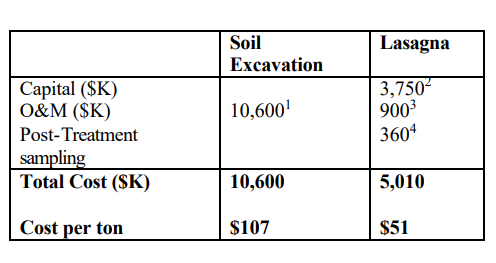
- Cost estimate includes excavation, transportation and land filling fees. Example assumed 30% of soil is disposed in a hazardous landfill and 70% in sanitary landfill.
- Capital includes installation, materials, rectifiers and other fixed costs.
- Operation is assumed to last one year. Costs include electricity and labor.
- Sampling costs are assumed to be an average of $6.50 per cubic meter ($5 per cubic yard).
7.0 ADVANTAGES AND DISADVANTAGES
7.1 Technology Advantages
Electrokinetics may be utilized for site remediation under conditions, which normally limit in situ approaches, such as in the case of the following:
⦁ Can treat both organic and Inorganic contaminants. Recovery of ionic contaminants by conventional means is complicated due to soil being a powerful ion exchange medium. Ionic contaminants are adsorbed and absorbed in soil particles, and are often not available for removal by the simple flushing action of groundwater. A pH shift must be applied to desorbs and mobilize the contaminants. However, flushing with strong acids usually destroys the basic soil structure, and may thus be self-limiting. Electrokinetics may be applied to mobilize contaminants without such concern, because acids are not pumped directly into the soil. Electrolysis of water in the circulating electrolyte produces the H+ ions at the anodes and the OH- ions at the cathodes. These ions migrate through the soil, generating a localized pH shift, which desorbs contaminating ions (Geokinetics, Inc. “Electrokinetic Remediation of Soil and Groundwater”, 1997 31]).
⦁ Effective even in soils of low hydraulic conductivity. Fine- grained sediments or low permeability soils present the greatest obstacle to in situ remediation at many contaminated sites. In clay and tight soils, hydraulic flow through fine pores is extremely limited, making these soils non-responsive to traditional soil flushing. Accessibility of the contaminants and delivery of treatment reagents have posed problems, rendering traditional technologies, such as vapor extraction and pump- and-treat, rather ineffective when applied to the low permeability soils present at many sites. Electrokinetics is an effective method of inducing movement of water, ions and colloids through fine-grained sediments
(Murdoch, et. al 1995) 4]
⦁ There currently are no other viable in situ methods of remediating heavy metals contamination from unsaturated soils. Excavating and processing, or disposal at a licensed landfill, will not always be feasible and will always be expensive (Electrokinetic Remediation of Heavy-Metal- Contaminated Unsaturated Soil 1995). If the total area of metals contamination is relatively small (1 acre or 0. Hectares) and highly concentrated, the application of a conventional technology like excavation or solidification might prove to be more economically feasible. But as excavation does not work well adjacent to buildings, small areas with high concentrations located in close proximity to structures may be more receptive to electrokinetics.
⦁ Allows treatment accessibility to soils not available for excavation.
When cost-effectiveness and technical feasibility of other remedial options prohibit their use, electrokinetic remediation may offer an alternative at sites contaminated with inorganic species.
7.2 TECHNOLOGY LIMITATIONS
Based on the results of laboratory tests and field applications, electrokinetics has been shown to be a promising method of covering ionic and water-soluble contaminants. However, the process has associated limitations, such as: (Murdoch, et. al 1995).4] The electrokinetic process is limited by the solubility of the contaminant and the desorption of contaminants from the soil matrix. Heavy metals in their metallic state have not been successfully dissolved and separated from soil samples.
- The process is also not efficient when the target ion concentration is low and non-target ion concentration is high.
- Acidic conditions and electrolytic decay can corrode some anode materials.
- Conventional electrokinetic remediation requires contaminants to migrate from their initial location to an electrode. In some cases, the migration path could be long or there could be stagnant zones between wells where the rate of migration is particularly slow, both of which result in incomplete remediation of the contaminated zone. Moreover, sharply convergent electrical fields can result in heating and potential losses in the vicinities of electrodes. A pH-related deposition can cause contaminants to be removed from solution prior to arrival at the ground surface of point of removal.
- Electrolysis reactions in the vicinity of the electrodes may cause changes in ambient pH that may change the solubility and speciation of the contaminants.
- Heterogeneities or subsurface anomalies at sites, such as building foundations, rubble, large quantities of iron or iron oxides, large rocks or gravel, or submerged cover materials such as seashells, can reduce removal efficiencies. Immobilization of metal ions by undesirable chemical reaction with naturally occurring and co-disposed chemicals can also occur.
- The presence of buried metallic conductors or insulators in the soil and reduction/oxidation and pH changes induced by the process electrode reactions can reduce the effectiveness of the process.
- Precipitation of species close to the cathode has been an impediment to the process. Heavy metals can prematurely precipitate close to the cathode at their hydroxide solubility value if the chemistry of the electrolyte at the electrodes is not altered or controlled (unenhanced electrokinetic remediation). Currently, studies conducted by Electrokinetics Inc. and the U.S. Army Waterways Experiment Station are underway to overcome the problem of precipitation close to the cathode, and the feasibility of employing different techniques to enhance the process are being evaluated. An objective of the studies is to promote transport of the positively charged species into the catholyte where they could be removed by electrodeposition, membrane separation, or ion exchange.
8.0 ELECTRODE EFFECTS
8.1 Corrosion Effects
The use of reactive metal electrodes eventually results in the accelerated corrosion of the electrode metal. The use of steel or copper electrodes causes anodic reactions of the electrode material, which are preferred over that of Hydrolysis of water. Aside from breakdown of the reactive metal to its ionic products, the reaction at the anode causes the suspension of water hydrolysis from taking place thus preventing generation of H+ ions, which in turn prevent the propagation of an acidic front that would have traveled through the soil. The prevention of acid generation through the soil may not be disadvantageous at all, if the objective is not to dissociate stable metals that are adsorbed by the soil and when only organic pollutants are targeted for removal.
In some instances, the use of reactive metals is objectionable, as the metallic breakdown products could in themselves become a source of pollution such as copper and other reactive metals. Thus, selective use of electrode materials could affect the conduct of the electrokinetic process and the generation of other species.
The use of reactive metals as electrodes such as steel produces different reactions. At the anodes, the preferential electrochemical reaction is with the more negative standard potential (voltage). At the cathodes, the opposite is true and preference is towards the more positive standard potential (voltage) Doering & Doering (2001) 3] illustrated this with the following half reactions:
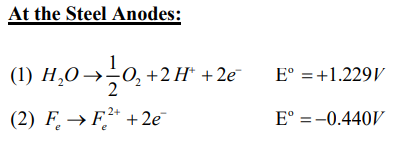
Thus, the reaction involving Iron (Fe) will prevail. The steel anode serves as a sacrificial anode and is oxidized since the (-) voltage predominates. Thus, the half reaction oxidative water electrolysis cannot take place.
In some specific instances, the use of reactive metal electrodes would be desirable in order to suppress generation of the Acidic front which could undesirably mobilize metallic compounds which otherwise could be safely “locked-in” and adsorbed by the soil.
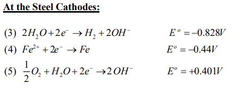
The positive potential E°=+0.401V in equation (5) predominates causing the increase in pH with the generation of 2OH-. However, in the field, it was observed. Doering & Doering (2001) 3]
Those additional reactions take place:
- Neutralization by CO2
- Formation of hydrocomplexes and decomposition of hydro complexes due to changes in pH.
- Natural buffer effects of the soil, which minimize the production of hydrogen.
The foregoing illustrates how by controlling the acid front, the mobilization or immobilization of heavy metals can be controlled through the use of reactive electrodes such as steel.
Also, in simple processes such as dewatering the soil, the EK process is primarily geared to inducing electroosmosis without the need for generating additional electrochemical reactions. In such cases, the use of inexpensive steel electrodes is indicated.
8.2 Use of Various Materials for Electrodes
More noble metals such as Titanium rods or titanium-plated rods have been used in order to prevent corrosion setup by preventing any anodic reactions of the base metal from taking place. Thus, only Hydrolysis reaction occurs allowing the generation of H+ ions and allowing the propagation of the acidic front as in the normal EK process. The same objective could be achieved using non- reactive electrodes such as Graphite or other Carbon electrodes.
In addition, non-reactive Titanium coated wire screens have been used in laboratory bench scale tests for research purposes.
The use of Carbon Electrodes in its various forms have also been successfully employed in order to prevent electrode reactions from taking place as well as be a cost effective substitute to more expensive metal electrodes.
9.0 DIRECTIONS FOR FUTURE RESEARCH
Electrokinetics is fast emerging as a cost effective In-situ and Ex-situ Soil remediation technology for the removal of Organic and Inorganic contaminants. Numerous field scale tests have proven the commercial viability and technical effectiveness of the process when compared to other commercially available methods. The ability of EK to enhance the removal process by various mechanisms has been shown to demonstrate its effectiveness in ground remediation technology. In addition, these mechanisms and their effects can be tailored or altered in order to:
- Speed up removal with the use of reagents, chemical surfactants etc.
- Lock in non-critical contaminants in the soil by immobilization
- Enhance removal of target contaminants while retarding some.
- Work with other Ground Remediation processes for overall system effectiveness:
- Enhance the effects of reactive barriers
- Introduce or inject biosurfactants to enhance bioavailability for Bacterial attack of Organic contaminants
- Assisted Increased generation of Acids for accelerated desorption of chemical species.
However, there is still a lot of ground to cover in this newly deployed technology, which are subject to further research and investigation. Among these are:
⦁ Electrode Material – Most field technologies use expensive non- reactive metals as electrodes such as Titanium or titanium coated metals. The consideration for the use of Carbon forms (Graphite, Activated Carbon or Carbon Fibers) needs to be further exploited, as these are relatively inexpensive and easier to produce. In addition, Carbon in its various forms is available and indigenous to almost all countries. Particularly in the third world, where Environmental controls in the past have been absent or sadly lacking, use of Locally available and cheap electrodes could render the technology available to the poorest of nations.
⦁ Study of various Electrode Geometries to enhance electroconductivity or allow increased surface area exposure. Use of hollowed out electrodes to allow pumping in and out of absorption media and chemicals to enhance the EK Process.
⦁ Electrical consumption- Electricity usage of the process although still reasonable can be further reduced to increase the cost effectiveness of the process. This can be addressed with the use of more electroconductive electrodes, enhancing the soil’s electroconductivity by addition of chemicals, etc.
⦁ Use in Hybrid technologies- recent advances have been made in this regard such as the use of EK with Reactive barriers, layered treatment systems such as the Lasagna process and use in conjunction with Biodegradation methods in the soils.
⦁ Research into other Reagents and chemical processes that can decompose the soluble organic contaminants or absorb contaminants for immobilization.
⦁ Introduce the use of chemical or active absorbents in the Electrode well such as actuated carbon to capture heavy metals or react with other chemical contaminants.
⦁ Coupling of external contaminant recovery systems into the EK hydraulic circuit to remove contaminants and cycle electrode well water to further enhance the EK Process.
10.0 SUMMARY
This paper has reviewed Electrokinetics from its historical evolution to what it is today as a viable technology for the In-situ and ex-situ remediation of contaminated materials. The review hopefully has provided for a better understanding of the Electrokinetic process including its applicability for various ground contamination situations.
While the Review does not claim to provide for a very thorough or complete and authoritative report on the “state of practice” or the “state of the Art”, it is hoped that this work can be used as a starting or “ jumping off” point by the readers to gain at least a basic or fundamental understanding of the Electrokinetic process and move onwards. Work in this topic is Dynamic and various sources in the Internet and from expected numerous to be published researches can add to the body of knowledge already presented herein to augment and update research in this field.
Significant advances and successful practical applications of the technology have spurred increased interest in this method for the in-situ removal or treatment of contaminated ground. Because of its versatility, Electrokinetics can be combined with other procedures and processes in order to remediate contaminated ground. In addition, Electrokinetics lends itself to enhancements by chemical means depending on the target pollutant.
Electrokinetics can also selectively target specific contaminants for removal, while immobilizing or locking other contaminants, which are best left in the ground where they cannot do significant damage nor be a source of significant groundwater contamination.
Numerous researches are currently ongoing in various parts of the world in order to further enhance the effectiveness and cost performance of Electrokinetics.
A better understanding of the process and its mechanisms are undoubtedly needed to foster more research and practical commercial applications of the Electrokinetic process. A clearer understanding no doubt can point the way to enhanced methods and optimization of the process leading to more widespread commercialization and practical cost effective solutions to serious ground pollution or contamination.
Particularly for third world countries where significant quantities of hazardous materials have been dumped into the ground and which threatens groundwater as well as the health of the populace, a cost effective deployment of Electrokinetics procedures for ground treatment using indigenous materials and technologies can help immensely in the removal of hazardous substances in the ground.
It is hoped that the objectives of this paper have been met and a clearer understanding of the Electrokinetic process is realized through this paper.
LIST OF REFERENCES:
⦁ Lageman, R., Pool, W. and Seffinga, G. (1989) “Contaminated Soil, Electroreclamation: Theory and Practice. Chemistry and Industry 8 585-590
⦁ Pamukcu S. (1997) “Electro-Chemical Technologies for In-Situ Remediation of Contaminated Subsurface Soils”. EJGE pp. 1-44.
⦁ Doering, F. and Doering, N. (2001) “Electrochemical Remediation Technologies for Soil and Groundwater”. Proceedings EREM 2001 3rd Symposium and Status Report on Electrokinetic Remediation. Published by AGK University of Karlsruhe. Chapter 4, pp. 3-17.
⦁ Murdoch, et. al. (1994) “Electrochemical Remediation of Soil and Groundwater”.
Electrokinetics, Inc.
⦁ Pamukcu, S. and Wittle, J.K. (1992), “Electrokinetic Removal of Selected Heavy Metals From Soil,” Environmental Progress, Vol. 11, No.3, pp. 241-250, American Institute of Chemical Engineers.
⦁ Wallmann, P.C., (1994). “Electrokinetic Remediation”. U.S. Department of Energy, DOE/EM-0138P, Office of Environmental Restoration and Waste Management, Office of Technology Development, Technology Catalogue, 5pp, available at ⦁ http://irridum.nttc.edu/env/tmp/008.html.
⦁ Cox, C.D., Shoesmith, M.A. and Ghosh, M.M. (1996). “Electrokinetic Remediation of Mercury Contaminated Soils Using Iodine/iodide Lixiviant,” Environmental Science and Technology, 1996, Vol. 30, No. 6, pp 1933-1983.
⦁ Electorowicz, M. & Ju, L. (2001) “Removal of PAH Using Electrokinetic Transport of Biosurfactants in Clayey Soil. Proceedings EREM 2001 3rd Symposium and Status Report on Electrokinetic Remediation. Published by AGK University of Karlsruhe. Chapter 15, pp. 3-12.
⦁ Francy, D.S., Thomas, J.M., Raynor, R.L. and Ward, C.H. (1991), “Emulsification of Hydrocarbon by Subsurface Bacteria”. Journal of Industrial Microbiology 8:237-246.
⦁ Acar, Y.B., Alshawabkeh, A., (1993), “Principles of Electrokinetic Remediation’” Environmental Science and Technology, vol. 27, No. 13, pp 2638.
⦁ Reed, B.E., Mitchelle, T.B. and Halfield, J.H. (1995), “Chemical Conditioning of Electrode Reservoirs during Electrokinetic Soil Flushing of Pb Contaminated Silt Loan”. J. Of Envir Eng 121 (11): 805-815.
⦁ Page, M.M. and Page, C.L. (2002), “Electroremediation of Contaminated Soils”.
J. Of Envir Eng March 2002. Vol. 128, No. 3 pages 208-219.
⦁ Ricart, M.T. (2001) “Removal of Multiple Metallic Species from a Sludge by Electromigration”. Proceedings EREM 2001 3rd Symposium and Status Report on Electrokinetic Remediation. Published by AGK University of Karlsruhe.
Chapter 9, pp. 4-10.
⦁ Shang, J.Q. (2000) “Electrokinetics in Geotechnical & Environmental Engineering Conference. Vol. 1, pp. 5-23.
⦁ Jones, CJFP et. al. (2002) “Soil Consolidation using Electrically Conductive Geosynthetics. Geosynthetics 7th ICG ISBN 90-5809 523 1, pp. 1039-1042.
⦁ Karunarathe, G.P. (2002) “”Electro-osmotic consolidation of soft clay based on Laboratory and Field Trials” Geosynthetics 7th ICG ISBN 90-5809 523 1, pp. 1043-
1046.
⦁ Cauwenberghe, Liesbet Van. (1997) “Electrokinetics – Technology Overview Report”. Ground-Water Remediation Technologies Analysis Center (GWRTAC).
⦁ Electrokinetics, Inc., “Bioremediation In Situ Groundwater”, available at http://bordeaux.uwaterloo.ca/bio1447/groundwater/bioremediation_in_situ_ground water.html.
⦁ “ElectroChemical GeoOxidation, ECGO”, ManTech International Corporation, 3pp., available at ⦁ http://mantech.com/environ/ecgo.htm.
⦁ “Electrochemical Oxidative Remediation of Groundwater”, 1997. SRI International, May 17, 1997, available at
http://www-mpl.sri.com/projects/pyu7459.html.
⦁ “Fuel Oils, DNAPL’s & Solvents – EH/DPE”. Geokinetics, available at ⦁ http://www.geokinetics.com/giievac.htm.
⦁ “Heavy Metals, Arsenic, Cyanide, etc. – Electrokinetic Remediation”
Geokinetics, 4pp, available at http: www.geokinetics.com/giiek.htm.
⦁ “Electrokinetics, Inc., (1994) “Electro-Klean Electrokinetic Soil Processing,” SITE Technology Profile-Demonstration Program, available at ⦁ http:www.gnet.org/gnet/tech/techdb/site/demongng/electkin.htm.
⦁ U.S. Environmental Protection Agency, 1996, “LasagnaTM Public-Private Partnership,” EPA542-F-96-010A, U.S. EPA Office of Research and Development, Office of Solid Waste and Emergency Response, September 1996, 4pp.
⦁ “U.S. Department of Energy (1996) “LasagnaTM Soil Remediation,” Innovative Technology Summary Report, U.S. DOE Office of Environmental Management, Office of Science and Technology, April 1996, summary available at ⦁ http://www.gnet.org/gn…ch/reports/lsr.htm#SUM.
⦁ “Complementary Technologies – Electrochemical Ion eXchange,” Geokinetics, 3pp., available at ⦁ http://www.geokinetics.com/giieix.htm.
⦁ Department of Energy, 1995, “Electrokinetic Removal of Heavy Metals from Soils”. October 20, 1995, 3pp, available at ⦁ http://www.em.doe.gov/rainplum/plum324.html.
⦁ ISOTRON Products and Services (1996) available at ⦁ http://www.isotron.com/products.htm.
⦁ “About the RTDF LasagnaTM Partnership,” Remediation Technology Development Forum, 1996, available at ⦁ http://www.rtdf.org/htmlpublic/lasagna/about.html.
⦁ “In Situ Solvent Remediation,” GE Research and Development, 4pp., available at http://www.crd.ge.com/el/aes/lasagne.htm
⦁ “Electrokinetic Remediation of Soil and Groundwater” (1997). SRI International, available at ⦁ http://www-mpl.sri.com/h[spinoffs]gii.html.
Ottosen, L.M. (1995) “Electrochemical Soil Remediation – Accelerated Soil Weathering?” Proceedings EREM 2001 3rd Symposium and Status Report on Electrokinetic Remediation. Published by AGK University of Karlsruhe.
Chapter 5, pp. 3-13.
Kristensen, I.V. (2001) “Electrochemical Removal of Cu, Cr and As from CCA- treated Waste Wood”. Proceedings EREM 2001 3rd Symposium and Status Report on Electrokinetic Remediation. Published by AGK University of Karlsruhe.
Chapter 7, pp. 3-10.
Boni, M.R. & D’Aprile, L. (2001) “Remediation of Soils Contaminated with Heavy Metals”. Proceedings EREM 2001 3rd Symposium and Status Report on Electrokinetic Remediation. Published by AGK University of Karlsruhe.
Chapter 10, pp. 3-8.
Suèr, P., Jönsson, S. & Allard, B. (2001) “Natural Organic Matter to Enhance Electrokinetic Transport of PAH”. Chapter 16, pp. 3-12.
Haus, R. Zorn, R., Czurda, K & Ruthe, H. (2001) “Electrokinetic Transport Behavior of Phenol in Upper Permian Soils”. Proceedings EREM 2001 3rd Symposium and Status Report on Electrokinetic Remediation. Published by AGK University of Karlsruhe. Chapter 24, pp. 3-13.
Krauss, H. Zorn, R., Haus, R. & Czurda, K. (2001) “Electroosmotic Transport in Fine Grained Sediments with Respect to Pore Throats. ´ Proceedings EREM 2001 3rd Symposium and Status Report on Electrokinetic Remediation. Published by AGK University of Karlsruhe. Chapter 31, pp. 3-12.
Chan, M. S. M., Lynch, R. J. & Ilett, D. J. (2001) “Use of Cation Selective Membrane and Acid Addition for ph Control in Two-Dimensional Electrokinetic remediation of Copper”. Proceedings EREM 2001 3rd Symposium and Status Report on Electrokinetic Remediation. Published by AGK University of Karlsruhe.
Schmid, M. & Marb, C. (2001) “Control of Electrode Processes in Electrokinetic Soil Remediation”. Proceedings EREM 2001 3rd Symposium and Status Report on Electrokinetic Remediation. Published by AGK University of Karlsruhe.
Gregolec, G., Zorn, R., Kurzbach, A., Roehl, K. E. & Czurda, K. (2001) “Coupling of Hydraulic and Electric Gradients in Sandy Soils”. Proceedings EREM 2001 3rd Symposium and Status Report on Electrokinetic Remediation. Published by AGK University of Karlsruhe.
Murdoch (1995) “Electrochemical Remediation of Heavy Metal Contaminated Unsaturated Soil”.
Murdoch, L., J. Chen, P. Cluxton, M. Kemper, J. Anno, D. Smith. “Hydraulic Fractures as Subsurface Electrodes: Early Work on the Lasagna Process,” Center for Geoenvironmental Science and Technology, Department of Civil and Environmental Engineering, 7pp, available at http://1286.70.23/html_docs/rrel/ murdoch.html.
Kim, S., Kim, K.W. Stuben, D. (2002) “Evaluation of Electrokinetic Removal of Heavy Metals for Tailing Soils”. August 2002. J. Of Envir Eng., Vol. 128 No. 8,
pp. 705-715.
Mohammeldasan, E., Shang, J.Q. (2001) “Analysis of Electrokinetic Sedimentation of Dredged Well and River Sediment”. J. Of Haz Materials 85 (2001) pp. 91-109
Micic, S., Shang, J.Q. (2002) “Electrokinetic Enhancement of Skirted Foundations embedded in Soft Marine Sediment”.
Fourie, A.B. et. al. (2002) “Stabilization of Mine Tailings Deposits using Electrokinetic Geotextiles”. Geosynthetics, pp. 1031-1034.
“Electrokinetic Remediation,” GNET, 10pp., available at http://www.gnet.org/forsite/?SubSystemID=1&ComponentID=1727.
Department of Energy (1995) “Field Demonstration of Electrokinetic Migration Technology at Old TNX Basin,” October 20, 1995, 3pp, available at http://www.em.doe.gov/rainplum/plum324..html.
Download A Review of the Electrokinetic Process for Soil Remediation (Rev. 1)