Emilio M. Morales, MSCE
1.INTRODUCTION
Earthworks and foundations invariably are part and parcel of any Civil Engineering Project. A significant portion of the overall project cost is often spent on Foundations Systems and Earthwork Compaction.
Particularly on sites with poor or marginal soils, there is a need to look into Ground Improvement in order to provide for economical foundation or earthworks.
Ground improvement can be in many forms, such as:
- Mechanical
- Chemical (Lime, Cement, Stabilization, etc.)
- Electrical
- Thermal
- Hydraulic (dewatering, PVD, etc.)
This paper will focus on Mechanical Ground Improvement because it is often the most misunderstood and the most often taken for granted.
In the case of mechanical stabilization, there are three zones of application namely:
- Near Surface Ground Improvement by Mechanical Compaction (Compactors)
- Intermediate Ground Improvement (Dynamic Compaction, Overexcavation & Replacement, Rammed Aggregate Piers)
- Deep Ground Improvement (Stone Columns & Vibroflotation)
This paper will try to discuss the foregoing zones of application and how applicable ground improvement procedures could be fully appreciated through an intimate understanding of Soil Mechanics Principles particularly as it pertains to Soil Particulate Behavior.
2.1 The Mechanics of Soils
Mechanical Ground Improvement most of the time can be a cost effective foundation solution if the fundamentals of soil mechanics and soil behavior are known to the user. The knowledge gained from this paper can be put to good use when Mechanical Ground Improvement is comtemplated.
For this paper, we shall only limit ourselves to a clear understanding of Particulate Mechanics or the behavior of soils as discrete particles when subjected to ground improvement.
2.2 Soil as a Particulate Material
Under very high magnification even a piece of solid mass of clay appears as an assemblage of particles with some orientation. This orientation surprisingly can be altered by mechanical reworking of the clay, addition of, or removal of moisture or by altering the chemical make-up of the porewater.
Under normal conditions, the assemblage includes water and air. The water is either captured or adsorbed water or free water.
The process of compaction is nothing but the expulsion of air and/or water (reduction of voids in the soil).
Soil can either be:
- Coarse Grained (Sand) or Cohesionless
- Fine Grained (clay) or Cohesive
The distinction between the two are somewhat obscured by their combinations that could be found in nature. In their unadulterated states, the differences become readily apparent.
2.3 Soil Shear Strength
Particulate materials derive their strength from friction or intergranular contact and/or from bonding forces or cohesion as we know it. These bonding forces and friction prevent the particles from sliding.
The important property that we have to deal with is the soils’ Shear Strength since most of the loading that the soil is subjected to causes the individual soil particles to slide or “shear” one against the other because of their particulate character.
The shear strength is either derived from electrical and chemical forces of attraction (cohesion) and repulsion as in clays or by simple grain to grain contact and friction as in Pure Granular Materials. Since shear strength depends on the sliding resistance of the individual soil particles. Therefore, the more compact the soil becomes, the higher the shear strength. To improve strength mechanically is to lessen the interparticle distances by the expulsion of air and/or water.
This leads us to one of the Fundamental Principles in Earth Compaction:
“Increasing Density (Strength) is achieved by decreasing the soil interparticle distance through the expulsion of air or water or both.”
Reduction of interparticle distances would sometimes require addition of more water into the soil in order to dislodge more water. This statement appears to be confusing but its proof reiterates the importance of the understanding of soil particulate behavior in the solution of Earthwork Problems.
2.4 Microstructure
2.4.1 Clay Microstructure
Shown below is a microscopic view of a sample of cohesive or fine grained clay soil .
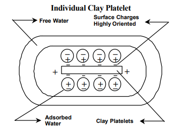
The clay is composed of submicroscopic platelets surrounded by Electrical charges, a closely held layer of adsorbed water and an outer layer of loosely held water. The minute interparticle distances, are governed not only by the particle orientation but also by the Electrical forces of attraction and the thickness of the adsorbed and free water. It would take a very high input of energy in order to dislodge or remove the adsorbed layer. The loosely held water can be removed in the field by sample air drying or wind rowing. When free water is removed, densification can be attained.
2.4.2 Sand Particles
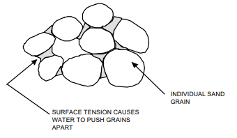
At a certain Moisture Content Water comes in-between and holds the grains apart by surface tension.
When grains of dry sand are gently deposited in a container, they fall into place in a precarious grain to grain contact. A jarring motion imparted on the container causes the grains of sand to assume a denser packing. Addition of water causes dry sand to swell or increase in bulk while saturation with water causes the sand to be compacted into a denser state. This has been known to us as “Hydrocompaction”. Perhaps only the mechanism behind it is not well understood.
3. NEAR SURFACE COMPACTION
3.1 Earth Compaction
Majority of efforts in Mechanical Ground Improvement is focused on general earthwork compaction.
Near surface compaction applies to compaction of Fills or subgrade materials by Mechanical Procedures.
In this section, we shall deal with compaction characteristics of soils and the applicable methods best suited for each type of soil.
We begin with the all too familiar moisture density relationship known as the “Laboratory Proctor Test” for a clay soils.
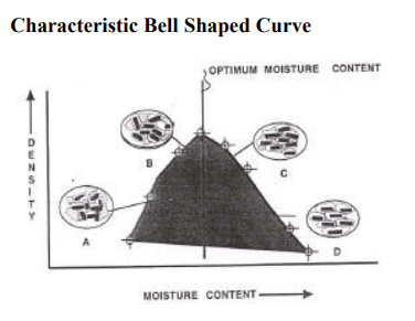
Familiarity with this simple bell shaped curve and its universal acceptance as the “characteristic” compaction curve cause most of the problems we encounter today in Earthworks compaction. Too often, it has not been realized that this is not the only shape a laboratory Proctor curve can assume and that grain size and moisture play a great part in influencing the shape of the compaction curve.
This bell shaped curve is only applicable for fine grained soils or soils with significant plasticity as to make it perform as a clay like soil.
At the start of the test when the soil is relatively dry, the soil assumes a flocculated structure “A”. Additional mechanical reworking and increasing amounts of water and expulsion of air and closing of the voids tend to produce a semi flocculated structure “B” with increasing density until a peak is attained. This peak is the maximum density that could be attained by that type of soil in the laboratory. The Degree of Compaction of the same soil in the field is expressed in terms of “Relative Compaction” which a percentage of the maximum dry density obtained in the laboratory test.
The moisture content corresponding to this maximum density is known as the Optimum Moisture Content “OMC”. Further compaction and additional water beyond this point results in decrease in density with increasing amounts of water. The soil platelets begin to be oriented and aligned and the interparticle distances tend to widen as more and more water is captured.
The “S” Curve
We now look at the Moisture Density relationship curve for a coarse grained sand with very little or no fines.
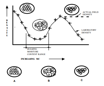
The curve is shaped like an “S”.
Since the individual grains are relatively very very large compared to the clay platelets, surface forces play very little influence on the behavior except at a certain moisture content range.
The Moisture Density curve above indicates two density Peaks “P1” and “P2” where density is high. The first Peak P1 occurs when the soil is very very dry (MC–>O) and the other Peak P2 at almost saturation conditions. Between these two Peaks is a valley where density is lowest.
The reduction in density in this valley as defined by a moisture content range is known as the “Bulking Range” for this particular sand.
This reduced density is caused by surface tension forces of the water surrounding the individual grains which tend to drive the adjacent grains farther apart, causing loss of interparticle contact and collapse in the density
from the previous high.
Progressive addition of water beyond the bulking range collapses the surface tension and the additional hammer impacts increases the density again to the second Peak “P2”. The laboratory curve shows a downhill movement in density with increasing moisture content beyond saturation levels.
The real field curve shown by the dotted line suggests otherwise. In the laboratory compaction procedure, the water can not drain within the steel compaction mold and thus the soil becomes a soupy mush. In the field, additional water is continually drained and the Peak density is maintained.
This curve clearly shows the fallacy of specifying Proctor Compaction Procedures and an OMC for clean coarse grained soils, because definitely, the soils are insensitive to moisture content except at the very dry and very saturated conditions. Unlike clay soils which follow a typical bell shaped curve, clean coarse grained soils exhibit a typical “S” shaped curve with the Peaks P1 & P2 clearly distinguishable.
Peaks P1 & P2 may sometimes be equal but this is more of an exception than the rule and their relative maximum values could shift either way depending on the type of soil.
This characteristic granular soil behavior has been recognized by the ASTM and standardized into two standards ASTM D-4253
“Max. Index Density of Soils using a Vibratory Table” ASTM D-4254 “Min. Index Density of Soils and Calculation of Relative Density” to arrive at a minimum and maximum density.
These values are then used to compute the Relative Density DR once the Field Density is obtained. Compaction is specified not in terms of % of Proctor MDD but rather as Relative Density DR .
Recognition of the two characteristic compaction curves (The “Bell” and the “S”) leads us to the realization that clays and sands behave very much differently when compacted and require different approaches and solutions.
We also know now that the behavior of soils can be tempered to suit our requirements. Thus, we are led to the following conclusions:
- There is not one but two General characteristic curves for soils depending on their granulometry.
- The concept of Optimum Moisture Content generally does not apply to Clean Granular Soils and therefore the Proctor Standard is inappropriate or could lead to problems in the Field. Clean sands either have to be compacte very very dry or very very wet in order to achieve the maximum density.
- The microstructure of the soil needs to be considered in the selection of the right compaction equipment.
- For Fine Grained Soils, although density is the same for corresponding points left and right of the OMC, the performance and behavior of the soil are different due to the alteration in the microstructure arrangement.
- Beyond the maximum density, additional compaction energy would be detrimental to both clays and sands as breakdown can occur causing a decrease in density. Therefore, use no more than what is necessary to attain good compaction.
- For intermediate soils, it would be necessary to determine in the laboratory the characteristic behavior from zero MC to saturation levels.
- In case the laboratory curve is not clearly defined or when there are doubts as to the behavior in the field, a field compaction trial would be required.
3.2 Compaction Equipment
Knowing the behavioral characteristics of soils we now look at the means to achieve compaction in the Field.
However, try to remember the fundamental response of the two general types of soils to compactive effort:
- Loose Clean Granular Soils because of their precarious grain to grain contact are best compacted by causing a jarring motion such as what a vibratory roller would impart.
- Fine Grained Soils on the other hand respond better to a kneading type of compactive effort such as that imparted by sheepsfoot rollers and pneumatic type rollers as these tend to reorient the platelets.
We now look at the Chart below to determine the range of applicability of various compaction equipment:
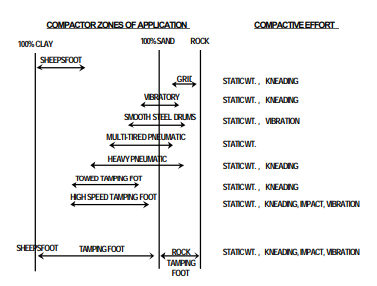
Figure 8.10 Compaction equipment selection guide.
This chart contains a range of material mixtures from 100 percent clay to 100 percent sand, plus a rock zone. Each roller type has been positioned in what is considered to be its most effective and economical zone of application. However, it is not uncommon to find them working out of their zones. Exact positioning of the zones can vary with differing mateial conditions.
We can therefore see the effective range for various compaction equipment under differing soil conditions and we recognize right away that this has something to do with the grain size (clay to rock).
3.3 Applications of Knowledge Gained
It is not only enough to know how to select the proper compactor for the job. It is also important to use this in conjunction with our knowledge of Soil Mechanics principles which we now apply:
3.3.1 Sands and Clean Coarse Grained Soils
Vibratory compaction works best. However, we should aid this by liberal application of water immediately ahead of the vibratory compactor. Coarse grained soils compact best at the very very wet condition “P2” or at very very dry condition “P1”. Water serves as a lubricator but its total absence also prevents capillary forces from impeding the rearrangement of soil grains into a denser packing. Speed of the vibratory compactor is also important and needs to be controlled to about 2 to 4 KPH. Vibratory frequency is essential and should nearly approach the natural frequency of the soils. Standard frequencies are in the range of 30 to 40 cps.
The static weight of the vibratory roller is also important since the dynamic force exerted on the soil is a function of the static weight. The wheels of the roller are either ballasted by water, sand or even slag in order to increase the static mass.
Because the vibratory roller causes an “advancing wave” on the top of the lift being compacted, Field Density Testing in order to be fair has to be done below this disturbed layer. It will normally be required to scrape the top 50 cms before seating the Field Density Plate in order to be able to test the actual condition of the specific lift.
Field Density testing using the Sand Cone Method (ASTM D-1556) requires extra care since the means to measure the volume is calibrated clean sand. Any jarring motion results in increased sand intake of the test hole resulting in bigger hole volume computed than the actual resulting in low compacted densities. This condition can also be caused by compaction equipment being allowed to operate very near a Field Density test in progress.
For clean coarse grained sands, moisture is irrelevant except for the total absence of it or its presence at saturation levels.
Thus, there is no such thing as an Optimum Moisture Content for clean granular soils and Proctor criteria is entirely inapplicable in this context.
3.3.2 Clays and Intermediate Soils
For Fine Grained Materials and intermediate soil types possessing significant plastic fines, sheepsfoot rollers or pneumatic tired rollers are best. The kneading action allows reorientation of the grain and allows expulsion of entrapped air.
The sheepsfoot was modelled really after the shape of a sheep’s foot perhaps based on the observations of Mr. Mc Adam. The tendency of the sheepsfoot is to walk-up by progressively compacting or densifying the lowermost layers first and walking upwards. Thus we see that topmost layers are slightly less compacted and therefore need to be bypassed when conducting a Field Density Test.
In contrast with clean coarse grained soils, compaction moisture content and the Proctor criteria are fully applicable and the control of moisture during compaction is a crucial factor in the attainment of proper compaction.
Static weight is also important as it increases penetration of the sheepsfoot and increases the force pressing the platelets together.
Speed is not so critical as it is the kneading action and coverage that is important.
Vibratory motion is not necessary and is in fact harmful as it can cause build up in pore pressures in the soil and also cause shear cracking.
4. INTERMEDIATE GROUND IMPROVEMENT
Intermediate Ground Improvement comes in many forms. However, the immediate objective is to produce a shallow or intermediate crust of soil that would be stiffer or denser than the original soil condition. Other mechanisms are involved depending on the procedure.
This crust can then be depended upon to carry most of the load and dissipate the contact pressure to the softer soils beneath it.
4.1 Overexcavation and Replacement
This is the most common but perhaps the most expensive except for relatively very shallow depths. The procedure consist of excavating the very poor soil and backfilling the excavation by the original soil or imported select Fill and compacting the replacement with fill in lifts.
The compacted Fill then becomes an Engineered Fill whose compaction has been carefully monitored and the resulting densities are carefully checked by performing Field Density Tests (FDT).
The method may prove to be difficult in the presence of a shallow water table or during the rainy season where the excavation can become flooded.
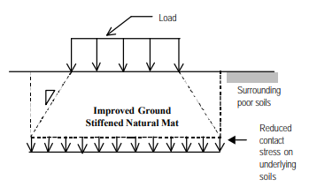
Creation of a controlled Engineered Fill or Backfill would entirely or partly eliminate the underlying poor soils and provide a stiffened natural mat which would reduce the contact stresses on the soils underneath it.
4.2 Dynamic Compaction or Heavy Tamping
Dynamic Compaction or Heavy Tamping is a procedure for compacting soils by dropping a heavy weight from a considerable height. The technique was invented by a Frenchman named Louis Menard. At that time, he called it “Dynamic Consolidation”, thinking that the process would be equally applicable to clays as well as granular materials. However, he would be proven wrong and the procedure is now concentrated on ground improvement of granular materials.
A very high impact energy is necessary to densify a thickness of soil to a depth ‘D’ in order to create a Densified Natural mat. The effective depth of treatment is empirically given as:
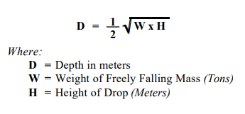
Heavy tamping, depending on the depth, would require several tamping passes. Each tamping pass requires the dropping of the weight to form a crater which is subsequently filled with Fill material to await the next pass. A sufficient time is allowed to elapse before the next pass is made to allow for pore pressure dissipation. The dissipation of pore pressure is monitored by use of piezometers in the ground installed specifically for this purpose. The method would be economical in large open areas that are not thickly populated or highly developed as the vibrations could affect surrounding areas.
Depth of treatment even from the very large energy machines is seldom beyond 10 meters as the impact energy is dissipated with depth.
An ironing pass is required at the end of the procedure as a levelling pass.
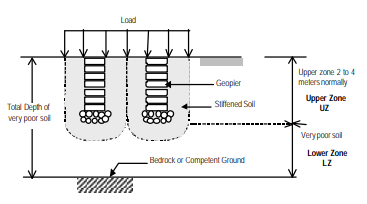
4.3 Intermediate Rammed Aggregate Piers (GEOPIER)
The Intermediate Rammed Aggregate Pier or GEOPIER is a proprietary technology developed to address the problem of shallow to intermediate depth ground improvement.
In contrast to overexcavation and replacement or Dynamic Compaction, the method does not rely only on improvement or stiffening of a soil layer. It also introduces prestraining of the surrounding soil though lateral compaction and outward push (straining) of the surrounding soil. The improvement of the soils by prestraining is achieved by introduction of a Rammed Aggregate Pier (The GEOPIER) into the soil by preaugering and compaction using high frequency, low amplitude tamping of successive lifts of ordinary base course aggregates.
The GEOPIER, because of its relatively very large stiffness compared to the surrounding soil, is able to sustain very heavy loads and assome a major share of the load. The stiffened soil surrounding the GEOPIER provides a greatly improved lateral support through Skin Friction.
The improvement in the lateral stress support is represented by the Mohr’s Circle Diagram below;
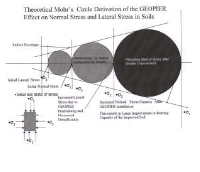
As can be seen, the initial state of stress is represented by the first circle where the Normal stress (σ1) is greater than the Lateral Stress (σ3). However, during the insertion and compaction of the GEOPIER (2nd Circle), the lateral stress is to increased Ko level, due to prestraining. Further buildup in lateral stresses elevates the lateral stresses allowing for a higher buildup in the normal stress.
Thus, the allowable load (Normal Stress) is substantially increased by the Rammed Aggregate Pier.
However, the load transfer mechanism is not as simple since a major share of the Normal Stress (load) is carried by the GEOPIER because of its relatively large stiffness compared to the surrounding soil matrix. The load is transferred to the GEOPIER and is carried through increased Skin Friction of the prestrained soil.
The GEOPIER transfers most of the load to the surrounding prestrained soil in this manner. As a result, it does not have to penetrate through very poor soil. For this reason, the Ground Improvement can be very very shallow but still have increased load capacity.
A load test is always necessary to validate the design assumptions and determine the actual GEOPIER Modulus.
Because of the increased frictional stresses induced along the GEOPIER shaft due to prestraining and prestressing of the surrounding soil, the GEOPIER has considerable uplift resistance. This makes it a very cost effective Tension Anchor with the incorporation of tension steel within the GEOPIER.
The GEOPIER has considerable uplift capacity because the failure cone of the soil is more developed.
Due to the use of common base course aggregates, simple construction equipment and shallow depth of installation, the method is a cost effective substitute to deep Piles, heavy tamping or overexcavation and replacement with Engineered Fill.
5. DEEP GROUND IMPROVEMENT
Deep very loose or poor Granular and Clay Soils are normally improved with the use of Granular Piles (Stone Columns, Sand Piles, Vibroflotation Piles). Generically, the procedure consists of inserting a vibrating probe or a casing into the loose soil with or without the aid of water jetting.
The cavity formed by displacement methods are then filled up with granular soils (sands or gravels) incrementally and compacted in lifts. The granular material is dropped down through the center of the probe with a bottom flap valve or the probe has to be withdrawn and material dumped into the cavity.
Because granular materials respond well to vibratory excitation, a very dense columnar granular Pile is formed with some densification of the surrounding soil being achieved. However, the radius of influence is very limited. These granular piles act as vertical load support elements to transmit the loads to more competent ground by point bearing and partly by Skin Friction. In addition, they can enhance the shearing capacity of the soil mass by providing stiff shear zones of highly compacted material. The composite ground consisting of vertical granular pile elements and the surrounding soil matrix is able to resist shearing better than the ordinary unreinforced soil.
Stress sharing also occurs between the granular piles and the surrounding soil although to a limited degree. The granular piles are normally installed at closer spacings in a triangular pattern as this gives the most dense packing of the granular piles for a given area.1]
A major share of the load is taken up by the pile because of this higher stiffness as compared to the surrounding soil matrix due to stress concentration.
Necessarily, the granular pile need to extend beyond the soft soil to a competent layer and therefore, the piles generally have to be deep. Thus, the load capacity is from the contribution of End Bearing and Skin Friction in much the same way as for conventional Piles.
The granular piles confer additional advantages such as:
- Reduced liquefaction potential as some densification occurs in the surrounding soils.
- Reduced pore pressure buildup during earthquakes which reduce potential for liquefaction, as the granular pile act as vertical sand drains to relieve pore pressures.
- Increased shearing capacity
- Preconsolidation effects due to the vertical sand drain effect.
Generally, the granular piles differ only in materials used and the method of installation.
The overall settlements is that of the composite ground and is calculated based on the area replacement ratio As and settlement reduction ratio.
There has been good performance record for stone columns particularly in Japan during the Kobe Earthquake.
Pier facilities on liquefiable ground that were reinforced by stone columns did not liquefy while the surrounding areas that were unreinforced, liquefied. The granular stone columns served as vents for the excess pore pressure, preventing buildup.
6. CONCLUSION
Mechanical Ground Improvement in order to be fully understood requires an intimate knowledge of soil behavior particularly as it refers to particulate soil mechanics.
Properly applied, Mechanical Ground Improvement is a cost effective measure to employ in the improvement of marginal lands.
The use of granular or Aggregate Piles also serve a double purpose. Aside from load support, the granular or aggregate pile body can serve as a vent to prevent the development of excess pore pressures. A new proprietary technology – Intermediate Rammed Aggregate Piers or GEOPIERS has been introduced to provide cost effective solutions to soft soil improvement and settlement control.
ABOUT THE AUTHOR
Emilio M. Morales, MSCE took up his masters degree at the Carnegie Institute of Technology, Carnegie -Mellon University, Pittsburgh, PA. USA in 1980. Formerly a Senior Lecturer of the Graduate Division, College of Engineering, University of the Philippines, Diliman, Quezon City. Presently, he is the Technical Manager of Philippine Geoanalytics, Inc. and was Chairman of the Cherry Hills Investigation Team (Joint PICE/ASEP).
He can be contacted at: Philippine Geoanalytics, Inc. PGA Technical Center #85 Kamuning Road, Quezon City. Telephone Nos. 929-33-54 Fax No. 929-33-53.
e-mail addresses: pgamain@pgatech.com.ph and emmorales@hotmail.com.